
2 ITEMSVIEW CART


Total: 20.00
Expert Support
Full Speed
100% Working
20 USD
Contents:
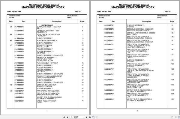
Boom Assembly – 4 Section 36’-114’
Cylinder Assembly – 6.50’’ Telescope
Nose Installation – Boom – Auxiliary
Sheave Assembly
Hook Block Assembly
Boom Extension Installation
Roller Assembly
Roller Assembly – Jib Cable
Sheave Assembly – Complete
Extension Assembly – Multiple Offset
Fly Assembly – Stinger
Boom Extension Alignment Device Installation
Carrier Installation – Boom Extension
Pat System Installation
Pat System Installation Basic Components – Lmi
Weight And Chain Assembly (Complete Assembly)
Cable Reel Assembly – Lwg221
Slip Ring Assembly – 11 Cond.
Console Assembly – Ds350gw With Light Bar Interface
Central Unit Assembly , Ds350g With Timer
Pat System Installation Console Assembly – Ds350g
Pat System Installation Console Assembly – Ds350gw
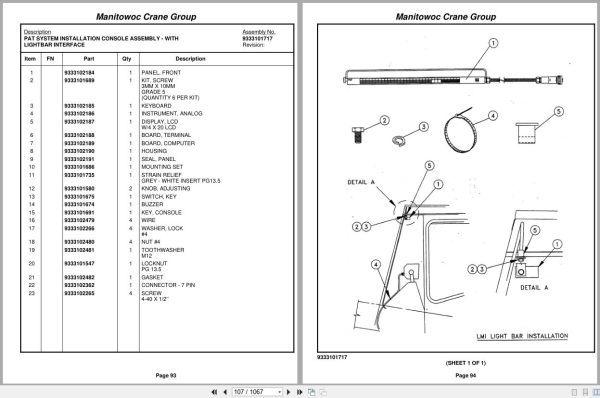
Pat System Installation Console Assembly – With
Pat System Installation Light Bar Installation –
Pat System Installation Cable Reel Assembly –
Pat System Installation Slip Ring Assembly –
Pat System Installation Central Unit Assembly – With
Pat System Installation Frame Assembly , Water
Pat System Installation Pressure Transducer
Pat System Installation 33’-58’ Tele Offset
Pat System Installation 33’ Offset Swing Away –
Pat System Installation 60’-88’ Lattice Jib – Lmi
Pat System Installation Auxiliary Boom Nose – Lmi
Pat System Installation Anti 2 Block Weight Assembly
Pat System Installation Minimum Layer Device
Pat System Installation Decal Installation – Ds350
Pat System Installation Wiring Diagrams
Pat System Installation Basic Components – Ei20
Console Assembly
Pat System Installation Reel Assembly – Cable
Pat System Installation Console Assembly – E120
Pat System Installation 33’ Offset
Pat System Installation 60’-88’ Lattice Jib – Ei20
Pat System Installation Auxiliary Boom Nose – Ei20
Valve And Pedal Installation – Swing Brake
Valve Assembly – Power Brake
Decal Installation – Rt990
Warning System Installation – Audio/Visual
Cab Installation
Cab Assembly
Cover Assembly – Valve
Valve Assembly – Transmission Shift Control
Control Assembly – (W/O Return To Center Steering)
Valve Assembly – Selector
Pedal And Valve Assembly – Accelerator
Valve Assembly – Control
Valve Assembly – Spring Brake
Valve Assembly – Dual Brake
Instruments And Lights Installation
Harness Assembly – Right Hand Side Console
Harness Assembly – Right Hand Front Console
Harness Assembly – Left Hand Front Console
Heater And Defroster Installation
Heater Assembly – Propane
Heater Assembly – Propane Circuit Board Assy
Heater Assembly – Propane Fuel And Ignition Systems
Heater Assembly – Propane Remote Control Parts
Heater Assembly – Propane Control Panel Parts
Heater Assembly – Propane Motor And Blower Parts
Heater Assembly – Propane Case And Exchanger Parts
Heater Assembly – Propane Regulator And Exhaust Parts
Grab Handle Installation
Weatherstrip Installation – Cab
Seat Installation
Seat Assembly
Fan Installation – Cab Circulating
Fan Assembly – 12 Volt Cab (Complete Assembly)
Acoustical Installation
Electrical System Installation
Harness Assembly – Superstructure
Harness Assembly – S/S Cab Interior
Fuse And Connector Panel Assembly
Harness Assembly – Connector Panel
Air Lines Installation –
Extinguisher Installation – Fire
Grab Rail Installation
Front Steer – Hydraulic Schematic
Control Lever Lockout Installation
Cylinder Assembly – Air
Skylight Wiper Installation
Load Chart Manual Installation
Control Valve And Linkage Installation
Valve Bank Assembly – 4 Section (A-35 Series)
Valve Assembly – Outlet
Valve Section – Inlet (A-35 Series)
Cartridge Assembly
Valve Assembly – 2 Section Control
Valve Bank Assembly – 2 Section (A-35 Series)
Valve Section – Outlet
Valve Bank Assembly – 1 Section (A-35 Series)
Valve Assembly – Relief 1000 Psi
Valve Bank Assembly – 1 Section
Valve Installation – Pressure Reducing
Valve Assembly – Pressure/ Reducing/Relieving
Panel Installation – Hydraulic Test
Hydraulic Lines Installation – Free Swing
Hydraulic Lines Installation – Inner Mid Telescope
Hydraulic Lines Installation – Outer Mid Telescope
Hydraulic Lines Installation – Fly Telescope
Hoist Installation – Main
Hoist Assembly – Model Ho-30b-26
Motor Assembly – Hydraulic
Brake Assembly
Cable Follower And Idler Installation
Cable Follower And Idler Assembly
Hoist Installation – Auxiliary
Idler Drum Assembly
Roller Assembly – Cable
Cable Follower Installation – Hoist
Hydraulic Lines Installation – Main And Auxiliary Hoist
Rotation Indicator Installation – Model 30
Driver Assembly Driver Assembly
Indicator Assembly
Transmitter Assembly
Turntable Drive Installation
Swing Box Assembly – Complete
Motor Assembly – Orbit
Brake Assembly – Swing
Bearing Bolt Installation
Lock Installation – Swing
Hydraulic Oil Cooler And By-Pass Valve Installation
Motor Assembly – Fan
Fan Assembly – Oil Cooler
Cooler Assembly – Oil
Swivel Installation – Electric/Air/Hydraulic
Swivel Assembly – 14 Port Hydraulic
Swivel Assembly – 12 Port Air/Hydraulic
Ring Assembly – Slip
Elevation And Swing Warning Installation
Hose Reel Installation
Reel Assembly – Hose
Counterweight Installation
Cylinder Installation – Lift
Cylinder Assembly – Lift
Valve Assembly – Overcenter
Shaft Installation – Boom Pivot
Hydraulic Lines Installation – Lift
Engine Installation – Cummins Nt855-C250
Radiator Installation
Exhaust System And Air Cleaner Installation
Cleaner Assembly – Air
Torque Converter Assembly
Torque Converter Assy. Group
Press. Reg.& Charge Pump Group
Pump Disconnect Assy. Group
Cylinder Assembly – Throttle
Pump Assembly – Steering
Pump Assembly – 3 Section
Battery Installation
Pump Disconnect Controls Installation
Pump Cover Installation
Quick Start Installation
Harness Assembly – Carrier
Alarm Installation – Back-Up
Belt & Filter Cumm. C250
Driveline Installation
Driveline Assembly
Transmission Installation
Transmission Assembly
Cylinder Assembly – Air Lockout
Valve Assembly Transmission
Axle Installation – Front
Axle Assembly
Axle Assembly Housing Assembly
Axle Assembly Hub And Shaft Group
Axle Assembly Differential Carrier Assembly
Axle Assembly Brake Assembly
Axle Assembly Fail Safe Brake Chamber
Axle Assembly Air Brake Chamber
Cylinder Assembly – Steer
Front Steer Relief Valve Installation
Valve Assembly – Relief
Axle Installation – Rear
Cylinder Assembly – 7″ Lockout
Rear Steer Indicator Installation
Valve Installation – Rear Axle Lockout
Valve Assembly – Lockout
Tire And Wheel Assembly
Tire Inflation Kit Installation
Tire Inflation Kit
Valve Assembly – Check
Hydraulic Lines Installation – Front Steer
Axle Lockout Hydraulic Schematic
Outrigger Beam Installation
Cylinder Assembly – Jack
Cylinder Assembly – 2 1/2″ Outrigger Extension
Valve Installation – Outrigger Control
Valve Assembly – 4 Stack Outrigger Solenoid
Valve Assembly – Integrated Outrigger
Outrigger Pad And Storage Installation
Float Assembly – Outrigger (Complete Assembly)
(Carrier) Hydraulic Lines Installation – Outrigger
Hood Installation – Engine
Door Assembly – Left Hand
Door Assembly – Right Hand
Fender And Battery Box Installation
Weather Stripping Installation
Filter Installation – Oil Converter
Filter Assembly – Oil
Hydraulic Reservoir Installation
Cover, Hydraulic Tank Installation
Tank Installation – Fuel
Tank Assembly – Fuel 100 Gallon
Tool Box And Ladder Installation
Turn Signal And Lights Installation
Dryer Assembly – Air
Rear View Mirror Installation
Hydraulic Lines Installation – Supply, Pressure And Return
Return Lines Installation – Manifold
Rear Steer – Hydraulic Schematic
Transmission And Converter Hydraulic Schematic

REALEASE :
REALEASE :

REALEASE :
REALEASE :

REALEASE :
REALEASE :

REALEASE :
REALEASE :

REALEASE :
REALEASE :

REALEASE :
REALEASE :

REALEASE :
REALEASE :

REALEASE :
REALEASE :
 Automotive - Heavy Equipment - Truck & Bus - Forklift - Crane