
2 ITEMSVIEW CART


Total: 20.00
Expert Support
Full Speed
100% Working
20 USD
Contents:
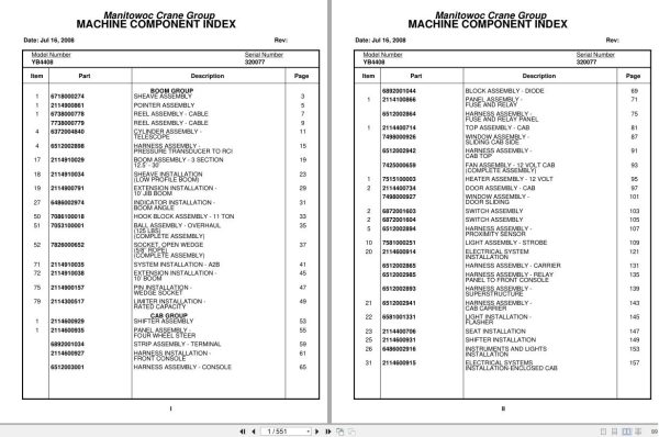
Boom Group
Sheave Assembly
Pointer Assembly
Reel Assembly – Cable
Reel Assembly – Cable
Cylinder Assembly –
Telescope
Harness Assembly –
Pressure Transducer To Rci
Boom Assembly – 3 Section
12.5’ – 30’
Sheave Installation
(Low Profile Boom)
Extension Installation –
10’ Jib Boom
Indicator Installation –
Boom Angle
Hook Block Assembly – 11 Ton
Ball Assembly – Overhaul
(125 Lbs)
(Complete Assembly)
Socket, Open Wedge
(5/8’’ Rope)
(Complete Assembly)
System Installation – A2b
Extension Installation –
10’ Boom
Pin Installation –
Wedge Socket
Limiter Installation –
Rated Capacity
Cab Group
Shifter Assembly
Panel Assembly –
Four Wheel Steer
Strip Assembly – Terminal
Harness Installation –
Front Console
Harness Assembly – Console
Block Assembly – Diode
Panel Assembly –
Fuse And Relay
Harness Assembly –
Fuse And Relay Panel
Top Assembly – Cab
Window Assembly –
Sliding Cab Side
Harness Assembly –
Cab Top
Fan Assembly – 12 Volt Cab
(Complete Assembly)
Heater Assembly – 12 Volt
Door Assembly – Cab
Window Assembly –
Door Sliding
Switch Assembly
Switch Assembly
Harness Assembly –
Proximity Sensor
Light Assembly – Strobe
Electrical System
Installation
Harness Assembly – Carrier
Harness Assembly – Relay
Panel To Front Console
Harness Assembly –
Superstructure
Harness Assembly –
Cab Carrier
Light Installation –
Flasher
Seat Installation
Shifter Installation
Instruments And Lights
Installation
Electrical Systems
Installation-Enclosed Cab
Panel Installation –
Relay
Extinguisher Installation
– Fire
Cab Installation –
Enclosed
Defroster Installation – Heater And
Bottle Installation –
Windshield Washer
Binder Installation
Control Valve Group – Upper
Valve Assembly – Control
Valve Assembly – Two
Section
Valve Assembly – Control
Valve Assembly – Three
Section
Unit Assembly –
Steering Control
Cylinder Assembly – Master
Valve Assembly – Park Brake
(Complete Assembly)
Accelerator Pedal Assy
Accelerator Pedal Design “B”
Accelerator Pedal Design “A”
Valve Assembly – Priority
Valve Assembly –
Dual Counterbalance
Valve Assembly – Two
Section Outrigger
Valve Assembly – Selector
Hydraulic Lines Installation –
Swing
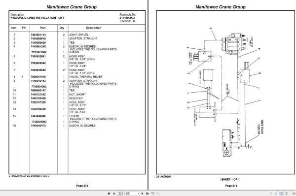
Hydraulic Lines
Installation – Lift
Hydraulic Lines Installation –
Telescope
Hydraulic Lines Installation –
Hoist
Hydraulic Lines Installation –
Pressure Check Panel
Hoist Group
Hoist Assembly
Carrier Assembly –
Primary
Carrier Assembly –
Secondary
Motor Assembly – Hydraulic
Valve Assembly – Motor
Control
Hoist Installation
Turntable Group
Bearing Bolt Installation
Cylinder Assembly – 7″
Lift
Swivel Installation –
Electric/Hydraulic
Cylinder Installation –
Lift
Shaft Installation –
Boom Pivot
Swivel Assembly –
Electric/Hydraulic
Swivel Assembly – 6 Port
Hydraulic
Slip Ring Assembly – 10
Conductor
Engine Group
Cleaner Assembly – Air
Radiator Assembly
Engine Installation –
(For Reference Only)
Battery Installation
Air Cleaner And Exhaust
Installation
Heater Installation – Block
Hood Assembly – Engine
Quick Start Installation
Radiator Installation
Hood Installation – Engine
Engine Component Assembly –
Cummins With Ford C-6 Transmission
(Not Available As Assembly)
Support Installation – Pump
Pump Assembly – Gear
Drive Train Group
Drive Line Assembly
Driveline Installation
Axle Group
Axle Assembly – Drive
Steer
Axle Assembly – Drive
Steer
Axle Assembly – Drive
Steer
Carrier Housing Parts
Axle Assembly – Drive
Steer
Differential Assembly
Axle Assembly – Drive
Steer
Axle Shaft Assembly
Axle Assembly – Drive
Steer
Disk Assembly
Cylinder Assembly – 3″ Steer
(Complete Assembly)
Hub And Spindle Assembly –
Right Hand
Hub Assembly
Chamber Assembly – Brake
Axle Installation –
Drive/Steer
Hub And Spindle Assembly –
Left Hand
Hub Assembly
Rear Steer Installation
Cylinder Assembly – 3″ Steer
(Complete Assembly)
Brake Installation – Park
Hydraulic Lines Installation –
Park Brake
Brake Lines Installation –
Front
Tire And Wheel Assembly
Lug Nut Installation
Outrigger Group
Cylinder Assembly-3″ Outrigger Extension
(Complete Assembly)
Outrigger Installation
Cylinder Assembly-3″ Outrigger Extension
(Complete Assembly)
(Complete Assembly)
Frame Group
Reservoir Assembly – Hydraulic
(Complete Assembly)
Filter Assembly – Return
Decal Installation – Standard
Decal Installation – Yb4408
Drive Assembly – Swing
Reducer Assembly – Planetary
Gear
Brake Assembly
Motor Assembly – Orbit
Valve Assembly – Cross
Relief
Hydraulic And Fuel Tank
Installation – Diesel
Frame Section
Stud Installation
Switch Modified –
Turn Signal
Exterior Light And Warning
Devices Installation
6376011270
Guard Installation –
Removable Light
Tie Down Installation –
Hook Block
Deck Cover Installation
Without Tow Winch
Cover Assembly – Tool Box
Mirror Installation
Kit, Hardware
Control Valve Group – Lower
Control Valve And Linkage
Installation
Hydraulic Lines Installation –
Supply, Pressure And Return
Hydraulic Lines
Installation – Outrigger
Hydraulic Lines Installation –
Front And Rear Steer
Schematic
Electrical Schematic
Hydraulic Schematic

REALEASE :
REALEASE :

REALEASE :
REALEASE :

REALEASE :
REALEASE :

REALEASE :
REALEASE :

REALEASE :
REALEASE :

REALEASE :
REALEASE :

REALEASE :
REALEASE :

REALEASE :
REALEASE :
 Automotive - Heavy Equipment - Truck & Bus - Forklift - Crane