
0 ITEMSVIEW CART


✓
Expert Support
✓
Full Speed
✓
100% Working
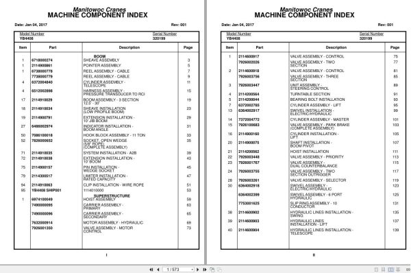
Grove Crane YB4408 320199 Parts Manual 2017
Size: 5.45 MB
Format: PDF
Language: English
Brand: Grove
Type of Machine: Crane
Type of Manual: Parts Manual
Model: Grove YB4408 Crane
Serial Number: 320199
Publication Date: 2017
Number of Pages: 573 Pages
30 USD
- Description
Description
Contents:
Boom
Sheave Assembly
Pointer Assembly
Reel Assembly – Cable
Reel Assembly – Cable
Cylinder Assembly –
Telescope
Harness Assembly –
Pressure Transducer To Rci
Boom Assembly – 3 Section
12.5′ – 30′
Sheave Installation
(Low Profile Boom)
Extension Installation –
10′ Jib Boom
Indicator Installation –
Boom Angle
Hook Block Assembly – 11 Ton
Socket, Open Wedge
(5/8” Rope)
(Complete Assembly)
System Installation – A2b
Extension Installation –
10′ Boom
Pin Installation –
Wedge Socket
Limiter Installation –
Rated Capacity
Clip Installation – Wire Rope
1114010000
Superstructure
Hoist Assembly
Carrier Assembly –
Primary
Carrier Assembly –
Secondary
Motor Assembly – Hydraulic
Valve Assembly – Motor
Control
Valve Assembly – Control
Valve Assembly – Two
Section
Valve Assembly – Control
Valve Assembly – Three
Section
Unit Assembly –
Steering Control
Turntable Section
Bearing Bolt Installation
Cylinder Assembly – Lift
Swivel Installation –
Electric/Hydraulic
Cylinder Assembly – Master
Valve Assembly – Park Brake
(Complete Assembly)
Cylinder Installation –
Lift
Shaft Installation –
Boom Pivot
Hoist Installation
Valve Assembly – Priority
Valve Assembly –
Dual Counterbalance
Valve Assembly – Two
Section Outrigger
Valve Assembly – Selector
Swivel Assembly –
Electric/Hydraulic
Swivel Assembly – 6 Port
Hydraulic
Slip Ring Assembly – 10
Conductor
Hydraulic Lines Installation –
Swing
Hydraulic Lines
Installation – Lift
Hydraulic Lines Installation –
Telescope
Hydraulic Lines Installation –
Hoist
Hydraulic Lines Installation –
Pressure Check Panel
Binder Installation
Superstructure Cab
Panel Assembly
Panel Assembly
Harness Installation –
Front Console
Harness Assembly –
Front Console
Strip Assembly – Terminal
Diode Assembly –
Block
Harness Assembly – Carrier
Panel Assembly – Relay
Harness Assembly – Fuse And
Relay Panel
Top Assembly – Open Cab
Harness Assembly – Relay
Panel To Front Console
Switch Assembly
Harness Assembly –
Superstructure
Harness Assembly –
Flasher Light
Instruments And Lights
Installation
Panel Installation – Relay
Binder Installation – Mini
Lowerworks/Carrier
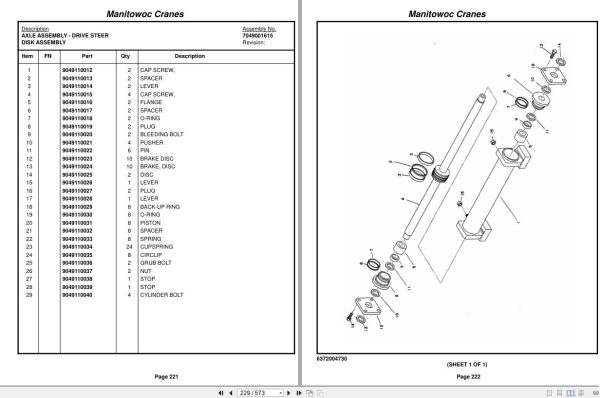
Axle Assembly – Drive
Steer
Axle Assembly – Drive
Steer
Axle Assembly – Drive
Steer
Carrier Housing Parts
Axle Assembly – Drive
Steer
Differential Assembly
Axle Assembly – Drive
Steer
Axle Shaft Assembly
Axle Assembly – Drive
Steer
Disk Assembly
Cylinder Assembly – 3″ Steer
(Complete Assembly)
Hub And Spindle Assembly –
Right Hand
Hub Assembly
Reservoir Assembly – Hydraulic
(Complete Assembly)
Filter Assembly – Return
Drive Line Assembly
Chamber Assembly – Brake
Cleaner Assembly – Air
Radiator Assembly
Axle Installation –
Drive/Steer
Hub And Spindle Assembly –
Left Hand
Hub Assembly
Rear Steer Installation
Drive Assembly – Swing
Reducer Assembly – Planetary
Gear
Brake Assembly
Motor Assembly – Orbit
Valve Assembly – Cross
Relief
Cylinder Assembly – 3″ Steer
(Complete Assembly)
Engine Installation –
(For Reference Only)
Battery Installation
Cylinder Assembly-3″ Outrigger Extension
(Complete Assembly)
Hydraulic And Fuel Tank
Installation – Diesel
Driveline Installation
Frame Section
Stud Installation
Brake Installation – Park
Hydraulic Lines Installation –
Park Brake
Air Cleaner And Exhaust
Installation
Switch Modified –
Turn Signal
Outrigger Installation
Brake Lines Installation –
Front
Cylinder Assembly-3″ Outrigger Extension
(Complete Assembly)
Control Valve And Linkage
Installation
Exterior Light And Warning
Devices Installation
Hydraulic Lines Installation –
Supply, Pressure And Return
Hydraulic Lines
Installation – Outrigger
Hydraulic Lines Installation –
Front And Rear Steer
Heater Installation – Block
Hood Assembly – Engine
Cover Installation –
Open Cab
Guard Installation –
Removable Light
Hookblock Tie-Down
Installation
Cover Installation – Deck
Lug Nut Installation
Quick Start Installation
Radiator Installation
Hood Installation – Engine
Mirror Installation
Kit, Hardware
Engine Component Assembly –
Cummins With Ford C-6 Transmission
(Not Available As Assembly)
Support Installation – Pump
Pump Assembly – Gear
Engine Assy-Cummins 4b3.9
Transmission Rework
Transmission-Ford C6
Case & Extension Assy. Group
Clutch, Direct Drive Group
Forward Clutch Group
Forward Hub & Gear Group
Reverse Clutch Group
Rev.Planet& Output Shaft Group
Control Linkage Group
Servo & Band Group
Control Valve Body Group
Rear Extension Housing Group
Transmission Kit
Electrical System Installation
Harness Assembly – Engine
Carrier/Frame Cab
Shifter Assembly
Light Assembly – Strobe
Switch Assembly
Harness Assembly –
Proximity Sensor
Accelerator Pedal Assy
Accelerator Pedal Design “B”
Accelerator Pedal Design “A”
Flasher Light Installation –
Open Cab
Seat Installation
Shifter Installation
Electrical System
Installation
Extinguisher Installation
– Fire
Specs/Schematics
Electrical Schematic
Hydraulic Schematic
Decals
Miscellaneous Decals
Decal Installation
Decal Installation – Yb4408
Related Products
-
Grove Parts Document Crane 7.82 Gb TM TMS TT TTS Series Collection PDF
250 USDThis is an offline spare parts catalog, you need to use this to sell the spare parts and it can help you a little with assembly. It’s from a manufacturer and the best in the world.Hot-38%
REALEASE :
REALEASE :
-
Grove RT EPC Spare Parts Catalog Manual 2023 PDF EN
600 USDThis is an offline spare parts catalog, you need to use this to sell the spare parts and it can help you a little with assembly. It’s from a manufacturer and the best in the world.Hot-70%
REALEASE :
REALEASE :
-
Grove Parts Document Crane GMK Series Collection 17.1 GB PDF
290 USDThis is an offline spare parts catalog, you need to use this to sell the spare parts and it can help you a little with assembly. It’s from a manufacturer and the best in the world.Hot-42%
REALEASE :
REALEASE :
-
Grove Crane AT ATS Series Collection Parts Document PDF 447 MB
70 USDIf you are a technician, You will need to use this product to repair your vehicleHot-83%
REALEASE :
REALEASE :
-
Grove GMK EPC Spare Part Catalog Manual 2023 PDF EN DE
70 USDThis is an offline spare parts catalog, you need to use this to sell the spare parts and it can help you a little with assembly. It’s from a manufacturer and the best in the world.Hot-88%
REALEASE :
REALEASE :
-
Grove Crane RT GRT Series Collection Parts Document PDF 43 GB
400 USDThis is an offline spare parts catalog, you need to use this to sell the spare parts and it can help you a little with assembly. It’s from a manufacturer and the best in the world.Hot-20%
REALEASE :
REALEASE :
-
Grove Crane 2024 Collection Parts Document 72.1 GB PDF
1,200 USDThis is an offline spare parts catalog, you need to use this to sell the spare parts and it can help you a little with assembly. It’s from a manufacturer and the best in the world.Hot
REALEASE :
REALEASE :
-
Grove Crane 1.8 Gb YB Series Collection Parts Document PDF
70 USDThis is an offline spare parts catalog, you need to use this to sell the spare parts and it can help you a little with assembly. It’s from a manufacturer and the best in the world.Hot-77%
REALEASE :
REALEASE :