
0 ITEMSVIEW CART

✓
Expert Support
✓
Full Speed
✓
100% Working
Lombardini Engine LDW502 Service Manual 1.5302.727
Size: 9.86 MB
Format: PDF
Language: English
Brand: Lombardini
Type of Machine: Engine
Type of Manual: Service Manual
Model: Lombardini LDW502 Engine
Part Number: 1.5302.727
Number of Pages: 98 Pages
10 USD
- Description
Description
Contents:
1 General Remarks And Safety
1.1 Purpose Of The Manual
1.2 Using This Manual
1.3 Manufacturer And Engine Identification
1.4 Glossary And Terminology
1.5 Warranty Clauses
1.6 General Safety Regulations
1.7 General Safety During Operating Phases 6
1.8 Safety And Environmental Impact
1.9 Precautions When The Engine Is Installed
On The Machine
1.10 Precautions When The Engine Is On The
Rotating Stand
2 Technical Information
2.1 General Description Of The Engine
2.2 Technical Specifications
2.3 Characteristic Curve Diagrams
2.4 Alternator Load Curve Diagrams
2.5 Lubricants
2.5.1 Sae Classification
2.5.2 Api/Mil Sequences
2.5.3 Acea Standards
2.5.4 Recommended Oil
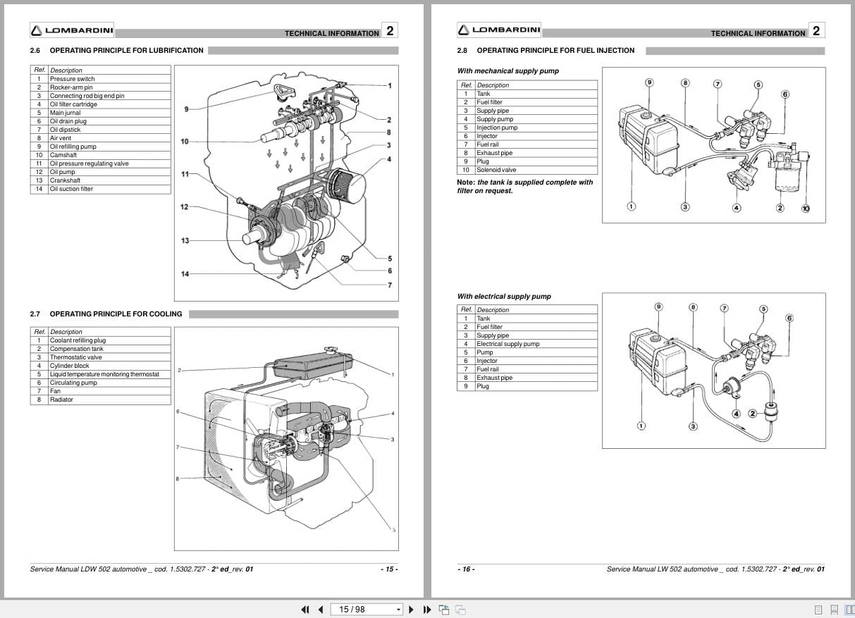
2.6 Operating Principle For Lubrication
2.7 Operating Principle For Cooling
2.8 Operating Principle For Fuel Injection
2.9 Wiring Diagram
2.10 Special Tools And Equipment For
Maintenance
2.11 Table Of Tightening Torques
2.12 Table Of Sealants
2.13 Routine Engine Maintenance
3 Malfunctions
3.1 Looking For Malfunctions
4 Storing The Engine
4.1 Handling And Lifting
4.2 Storing The Engine (Uninstalled)
4.3 Storing The Engine (Installed)
4.4 Protective Treatment
4.5 Preparing The Engine For Operation
(Uninstalled)
4.7 Preparing The Engine For Operation
(Installed)
5 Removing The Assemblies
5.1 Recommendations For Removing The
Assemblies
5.2 Removing The Exhaust And Intake
Manifolds
5.2.1 Disassembling The Intake Manifold
5.2.2 Disassembling The Exhaust Manifold
5.3 Removing The Cooling Fan Belt Drive
5.3.1 Disassembling The Cooling Fan Belt
(With External Alternator)
5.3.2 Disassembling The Cooling Fan Belt
(With Internal Alternator)
5.4 Removing The Timing Belt Drive
5.4.1 Disassembling The Timing Belt Casing
5.4.2 Disassembling The Timing Belt
5.4.3 Disassembling The Pulleys
(Camshaft And Crankshaft)
5.5 Removing The Cylinder Head
5.5.1 Disassembling The Rocker Arm Cover
5.5.2 Disassembling The Rocker Arms
5.5.3 Disassembling The Fuel Pump
5.5.4 Disassembling The Injection-Pumps
5.5.5 Disassembling The Precombustion Chamber
5.5.6 Disassembling The Speed Governor
And Flow Limiter
5.5.7 Disassembling The Camshaft
5.5.8 Disassembling The Cylinder Head
5.6 Removing The Crank Gear
And Crankcase
5.6.1 Disassembling The Flywheel
5.6.2 Disassembling The Oil Pump
5.6.3 Disassembling The Crankcase And Crankshaft
5.6.4 Disassembling The Connecting Rod And Piston
5.7 Disassembling The Valves
5.8 Disassembling The Piston
6 Overhauls And Tuning
6.1 Recommendations For Overhauls
And Tuning
6.1.1 Shaft Seals
6.1.2 O-Rings
6.1.3 Bearings
6.2 Overhauling The Crank Gears And
Crankcase
6.2.1 Overhauling Cylinders And Pistons
6.2.2 Dimensional Check And Overhaul Of Cylinders
6.2.3 Dimensional Check And Overhaul Of Pistons
6.2.4 Dimensional Check Of Sealing Rings
6.2.5 Dimensional Check And Overhaul Of Crankshaft
6.2.6 Dimensional Check And Overhaul Of
Connecting Rods
6.2.7 Checking Parallelism Of The Connecting Rod Axes
6.2.8 Checking And Overhauling The Fuel Pump
6.2.9 Overhauling The Decanting Device
6.3 Overhaul Of Cylinder Head And Related
Components
6.3.1 Checking And Overhauling The Cylinder Head
6.3.2 Checking And Overhauling The Rocker Arm Pin
6.3.3 Checking And Replacing The Camshaft
6.3.4 Checking And Replacing The Fuel Pump Drive Rod
6.3.5 Checking And Overhauling The Valves
6.3.6 Adjusting Valve-Rocker Arm Clearance
6.3.7 Checking Clearance Volume
6.3.8 Calibrating The Injector
6.3.9 Checking And Overhauling The Speed Governor
6.4 Checking Timing Belt Rating
6.4.1 Valve Adjustments
6.5 Diagram Of Timing Belt Rates
6.6 Adjusting Static Injection Timing
6.7 Balancing Injection-Pump Delivery
6.8 Adjusting Minimum And Maximum
Idle Speed Rpms
6.9 Adjusting Injection Delivery
6.9.1 Adjusting Injection Delivery (Without Dyno Brake)
6.9.2 Adjusting Injection Delivery (With Dyno Brake)
6.10 Checking Oil Pressure
7 Installation Of Assemblies
7.1 Recommendations For Installing The
Assemblies
7.2 Pre-Assembly Of
Sealing Rings – Pistons
7.3 Pre-Assembly Of
Connecting Rods – Pistons
7.4 Installing Valves
7.4.1 Assembling The Valves
7.5 Installation Of Crank Gear
And Crankcase …
7.5.1 Installing Piston/Connecting Rod – Engine Block
7.5.2 Assembling The Crankshaft
7.5.3 Assembling The Crankcase
7.5.4. Measuring Crankshaft Axial Clearance
7.5.5 Assembling The Crankshaft Flange (Flywheel Side)
7.5.6 Installing The Oil Pump
7.5.7 Assembling The Flywheel
7.6 Installation Of Cylinder Head And
Components…
7.6.1 Assembling The Precombustion Chamber
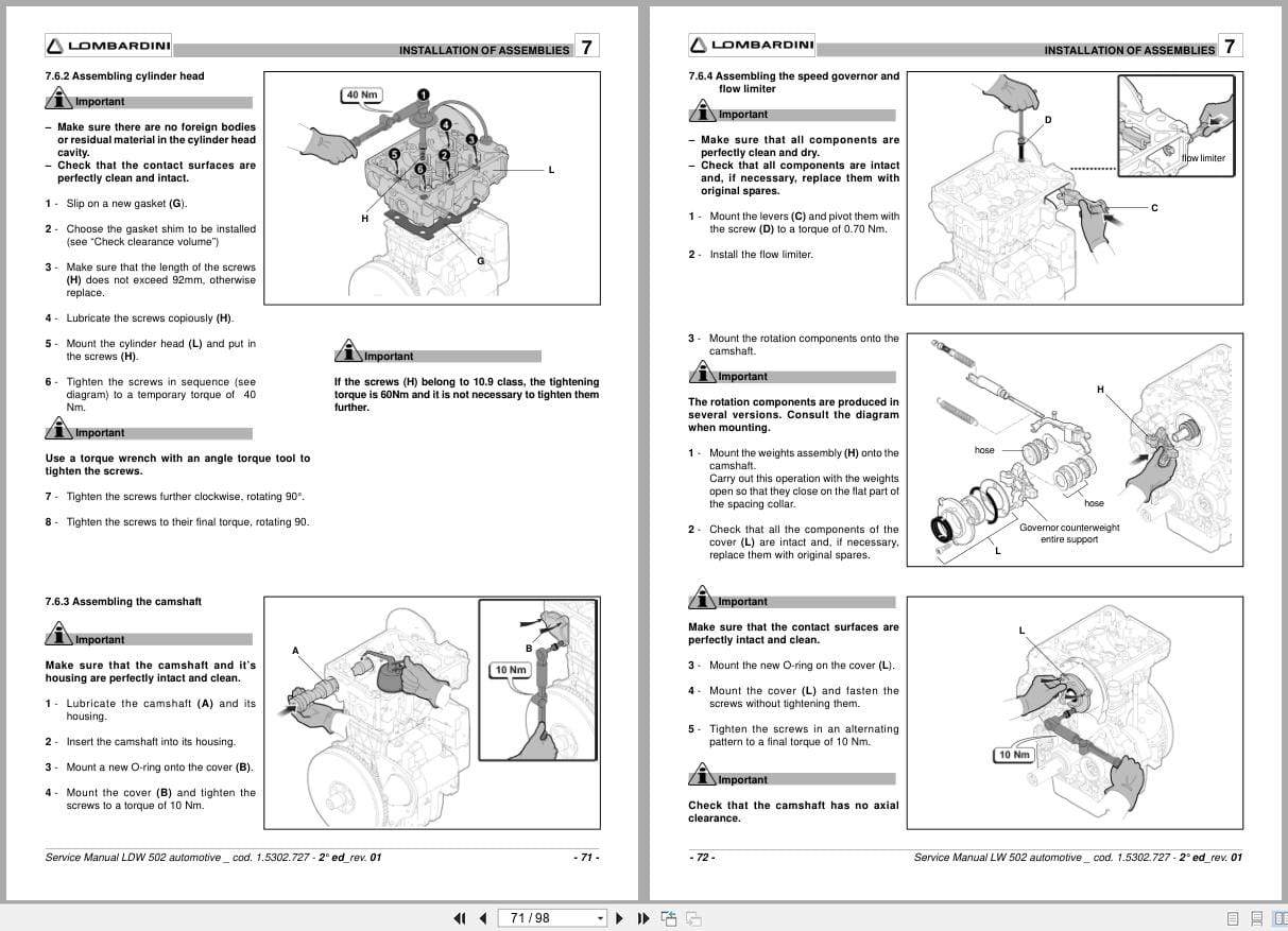
7.6.2 Assembling The Cylinder Head
7.6.3 Assembling The Camshaft
7.6.4 Assembling The Speed Governor And Flow Limiter
7.6.5 Assembling Injection – Pumps
7.6.6 Assembling The Mechanical Fuel Pump
7.6.7 Assembling The Rocker Arms
7.6.8 Assembling The Rocker Arm Cover
7.7 Installing The Timing Belt Drive
7.7.1 Assembling The Timing Belt Pulley
7.7.2 Assembling The Timing Belt
7.7.3 Assembling The Belt Drive Cover
7.8 Installation Of The Cooling Fan
Belt Drive
7.8.1 Assembling The Fan Belt Drive Pulleys
7.8.2 Assembling The Fan Belt Drive
7.8.3 Assembling The Cooling Fan
7.9 Installing Intake And Exhaust Manifolds 80
7.9.1 Assembling The Exhaust Manifold
7.9.2 Assembling The Intake Manifold
8 Replacing Parts
8.1 Recommendations For Replacing Parts
8.2 Replacing The Alternator – Fan Belt
8.3 Replacing The Timing Belt
8.4 Replacing The Oil Filter
8.5 Replacing The Air Filter
8.6 Replacing The Alternator
8.7 Replacing The Starter Motor
8.8 Replacing The Flywheel Ring Gear
8.9 Replacing The Coolant Thermostat
8.10 Replacing The Coolant Pump
8.11 Replacing The Thermostatic Valve …
8.12 Replacing The Negative-Pressure Vent
Valve
8.13 Replacing The Pre-Heating Glow Plugs
8.14 Replacing Injector Pump Parts
8.14.1 Pumping Element Replacement
8.14.2 Replacing The Nozzle-Injector
8.15 Replacing The Cooling Fan Support
Index
Related Products
-
Yanmar Engine 3TNV88C-KHW Parts Catalog 0CD50-M04200EN 2018
10 USDSize: 1.72 MBFormat: PDFLanguage: EnglishBrand: YanmarType of Machine: EngineType of Manual: Parts CatalogThis Parts Catalog Is The 1st Edition Of 3TNV88C-KHWModel: Yanmar 3TNV88C-KHW EngineApplication Model: Hako Citymaster 650 Rider SweeperPart Number: 0CD50-M04200ENPublication Date: 2018Number of Pages: 27 Pages
REALEASE :
REALEASE :
-
Yanmar Engine SMARTASSIST-Direct Operation Manual 0AYSA-EN0018 2018
10 USDSize: 46.31 MBFormat: PDFLanguage: EnglishBrand: YanmarType of Machine: EngineType of Manual: Operation ManualModel: Yanmar SMARTASSIST-Direct EnginePart Number: 0AYSA-EN0018Publication Date: 2018Number of Pages: 430 Pages
REALEASE :
REALEASE :
-
Hako Spare Parts List Machine Collection 456 MB Operating Manual
45 USDThis is an offline spare parts catalog, you need to use this to sell the spare parts and it can help you a little with assembly. It’s from a manufacturer and the best in the world.Hot-55%
REALEASE :
REALEASE :
-
Yanmar Engine 3TNV88C To 4TNV98CT Troubleshooting Manual 0DTN4-G00200 2015
10 USDSize: 19.34 MBFormat: PDFLanguage: EnglishBrand: YanmarType of Machine: EngineType of Manual: Troubleshooting ManualModel: Yanmar 3TNV88C 3TNV86CT 4TNV88C 4TNV86CT 4TNV98C 4TNV98CT EnginePart Number: 0DTN4-G00200Publication Date: 2015Number of Pages: 404 Pages
REALEASE :
REALEASE :
-
Hako EPC Spare Parts List PDF 8.59GB
110 USDThis is an offline spare parts catalog, you need to use this to sell the spare parts and it can help you a little with assembly. It’s from a manufacturer and the best in the world.Hot-45%
REALEASE :
REALEASE :
-
Yanmar Engine 3TNV88C-KHW Error Diagnostic Trouble Codes Wiring Diagram
10 USDSize: 11.49 MBFormat: PDFLanguage: EnglishBrand: YanmarType of Machine: EngineType of Manual: Error Code List, Diagnostic Trouble Codes, Electrical SchematicModel: Yanmar 3TNV88C-KHW EngineApplication Model: Hako Citymaster 650 Rider SweeperPublication Date: 2021Number of Pages: 52 Pages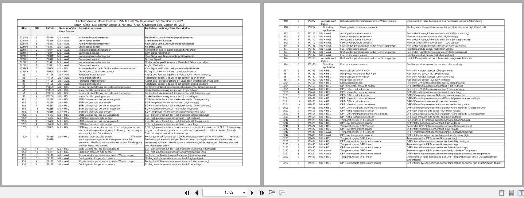
REALEASE :
REALEASE :
-
ZF Transmission GK20LD Spare Parts List
10 USDSize: 0.33 MBFormat: PDFLanguage: EnglishBrand: ZFType of Machine: Drive SystemType of Manual: Spare Parts ListModel: ZF GK20LD Drive SystemPublication Date: 2006Number of Pages: 7 Pages
REALEASE :
REALEASE :
-
Yanmar Engine 3TNV88C-KHW Error Code Electrical Schematic
10 USDSize: 27.90 MBFormat: PDFLanguage: EnglishBrand: YanmarType of Machine: EngineType of Manual: Error Code, Electrical SchematicModel: Yanmar 3TNV88C-KHW EngineApplication Model: Hako Citymaster 650 Rider SweeperPublication Date: 2021Number of Pages: 52 Pages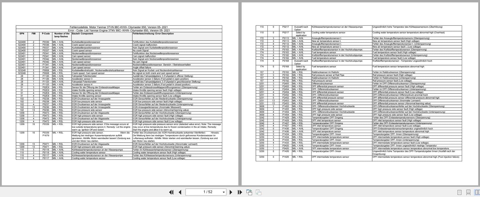
REALEASE :
REALEASE :