Expert Support
Full Speed
100% Working
Liebherr Telescopic Handler T435 T442 T445 Service Manual And Diagram
100$ USD
- Description
Description
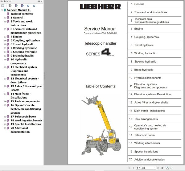
Contents:
1 General
1.1 Foreword and explanations
1.2 Safety guidelines
1.3 Tables
1.4 Conversation guidelines
1.5 Material weights
2 Tools and work instructions
2.1 Special tools
2.2 Repair welding
2.3 Assembly instructions
3 Technical data and maintenance guidelines
3.1 Technical data
3.2 Maintenance and inspection schedule
3.3 Maintenance and inspection guidelines
3.4 Adjustment check list
3.5 Inspection and adjustment tasks
4 Engine
4.1 Data page
4.2 Fan and cylinder arrangement
4.3 Installation kit Liebherr- Diesel particle filter
4.4 Installation and check list for Diesel particle filter
5 Coupling, splitterbox
5.1 Data page
5.2 Coupling
5.3 Splitterbox
6 Travel hydraulic
6.1 Data page
6.2 Design
6.3 Function
6.4 Repair work and troubleshooting
6.5 Component arrangement
7 Working hydraulic
7.1 Data page
7.2 Design
7.3 Function
7.4 Repair work and troubleshooting
7.5 Component arrangement
8 Steering hydraulic
8.1 Data page
8.2 Design
8.3 Function
8.4 Repair work and troubleshooting
8.5 Component arrangement
9 Brake hydraulic
9.1 Data page
9.2 Design
9.3 Function
9.4 Repair work and troubleshooting
9.5 Component arrangement
10 Hydraulic components
10.1 Variable displacement pump – Travel hydraulic
10.2 Variable displacement motor – Travel hydraulic
10.3 Regulating pump – Working hydraulic
10.4 Fixed displacement pump
10.5 Gear motor – Fan drive
10.6 Steering aggregate
10.7 Proportional control valve block
10.8 S / W Control valve block
10.9 Brake cylinder
10.10 Valves
10.11 Hydraulic cylinder
11 Electrical system – Diagrams and components
11.1 Component description
11.2 Function Chart
11.3 Fuses and notes
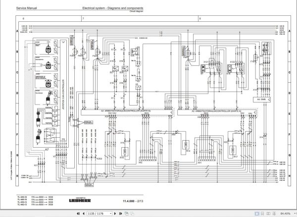
11.4 Circuit diagram
11.5 Component arrangement
11.6 Control lever / Joystick
11.7 Calibration of the electronic load display
11.8 DMS Sensor Installation
12 Electrical system – descriptions
12.1 Evaluation software Travel hydraulic LinDiag
12.2 Software for working hydraulic control Bodem
Software for Working hydraulic control BODAS
12.3 Service Code list
12.4 Software PDL – Diesel particle filter
13 Axles / tires and gear shafts
13.1 Data page
13.2 Design of axles and gear shafts
13.3 Disk brake
13.4 Differential
13.5 Wheel hub with steering axle
13.6 Gear shafts
14 Main frame – Installations
14.1 Level regulation
14.2 Support / side offset
14.3 Cooler arrangement
14.4 Engine mount
14.5 Battery installation
15 Tank arrangements
15.1 Hydraulic tank
15.2 Fuel tank
16 Operator’s cab, heater, air conditioning system
16.1 Operator’s cab
16.2 Heater with blower
16.3 Air conditioning system
17 Telescopic boom
17.1 Design and function
17.2 Repair instructions
18 Working attachments
18.1 Tool coupler
18.2 Forklift
18.3 Bucket
18.4 Aerial work platform
19 Special installations
19.1 Industrial control
19.2 Rear axle oscillation lock
19.4 Quick coupler
19.5 Reversible fan
19.6 Towing hitch device
19.7 Telescope – Leak oil line
20 Additional documentation
6.3 Schematic Travel hydraulic
7.3 Schematic Working hydraulic
8.3 Schematic Steering hydraulic
9.3 Schematic Brake hydraulic
11.4 Schematic Circuit diagram
14.1 Schematic Level regulation
14.2 Schematic Support
18.4 Schematic Aerial work platform
19.1 Schematic Industrial operation


