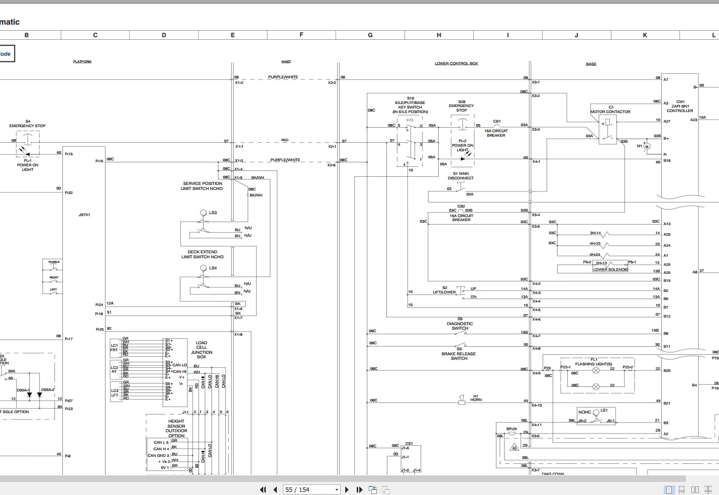
Total: 100.00
Expert Support
Full Speed
100% Working
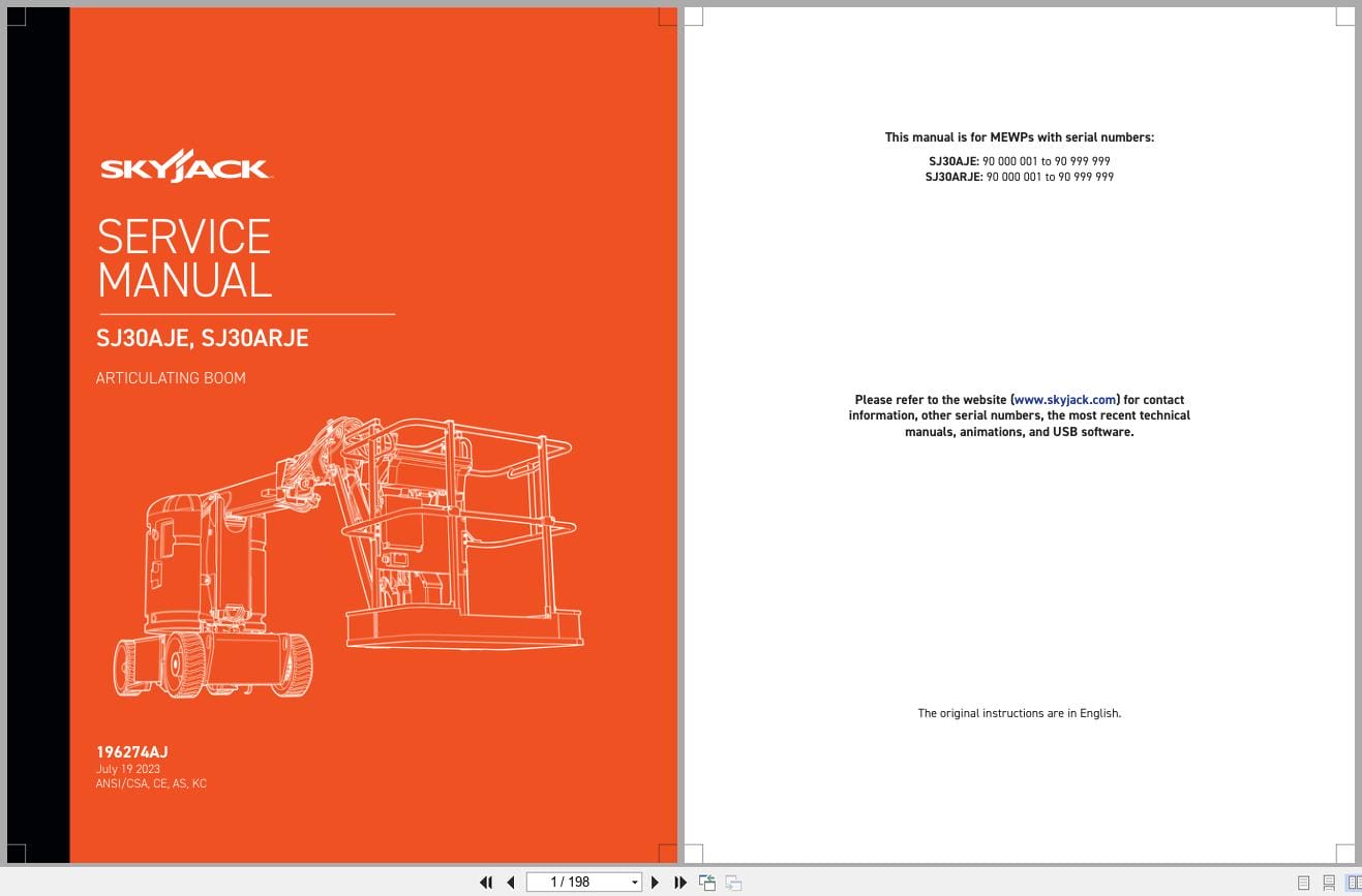
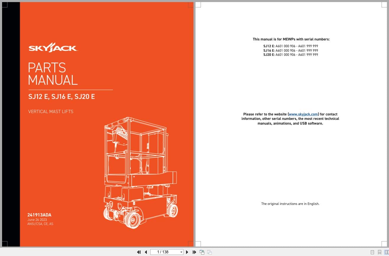
Skyjack Articulating Boom Lift SJ30AJE SJ30ARJE Service Manual 196274AJ 2023
20 USD
- Description
Description
Contents:
Section 1 – Scheduled Maintenance
1.1 Read and Heed
1.2 Maintenance and Service
1.3 Scheduled Maintenance
1.4 Owner’s Annual Inspection Record
1.5 Pre-Delivery/Maintenance Inspection Checklist
1.6 Scheduled Maintenance Inspections
1.7 Function Tests
Section 2 – Maintenance Tables and Diagrams
2.1 Standard Hose Numbering System
2.2 MEWP Torque Specifications
2.3 Torque Specifications for Fasteners (US)
2.4 Torque Specifications for Fasteners (Metric)
2.5 Torque Specifications for Hydraulic Couplings & Hoses
2.6 Tire Specifications
2.7 Maximum Platform Capacities
2.8 Floor Loading Pressure
2.9 Hydraulic Specifications
2.10 Gear Oil
2.11 Specifications and Features – ANSI/CSA
2.12 Specifications and Features – CE, AS & KC
2.13 Reach Diagram – SJ30AJE
2.14 Dimesion Diagram – SJ30AJE
2.15 Reach Diagram – SJ30ARJE
2.16 Dimension Diagram – SJ30ARJE
Section 3 – System Component Identification and Schematics
3.1 Electrical Symbol Chart
3.2 Hydraulic Symbol Chart
3.3 Wire Number and Color Code
3.4 Hydraulic Parts List
3.5 Electrical Parts List
3.6 Jib Valves and Port Identifications
3.7 Main Manifold Hose Port Identification
3.8 Main Manifold Electrical Component Identification
3.9 Main Manifold Component Identification
3.10 Main Manifold Harness – ANSI/CSA, CE & AS
3.11 Main Manifold Harness – KC
3.12 Platform Manifold Harness – SJ30 AJE
3.13 Platform Manifold Harness – SJ30 ARJE
3.14 Control Cables & Harnesses
3.15 Platform Limit Switch Harness – KC
3.16 Emergency Pump Base Controls Wiring
3.17 Direction Sensing Limit Switch Base Control Wiring
3.18 High Speed Cut – Out Limit Switches Base Controls Wiring
3.19 Overload Sensor Platform Controls Wiring
3.20 Footswitch Platform Controls Wiring
3.21 SGE Platform Controls Wiring
3.22 Motor Controller Wiring
3.23 Motor Controller Panel Schematic
3.24 Motor Controller Harness
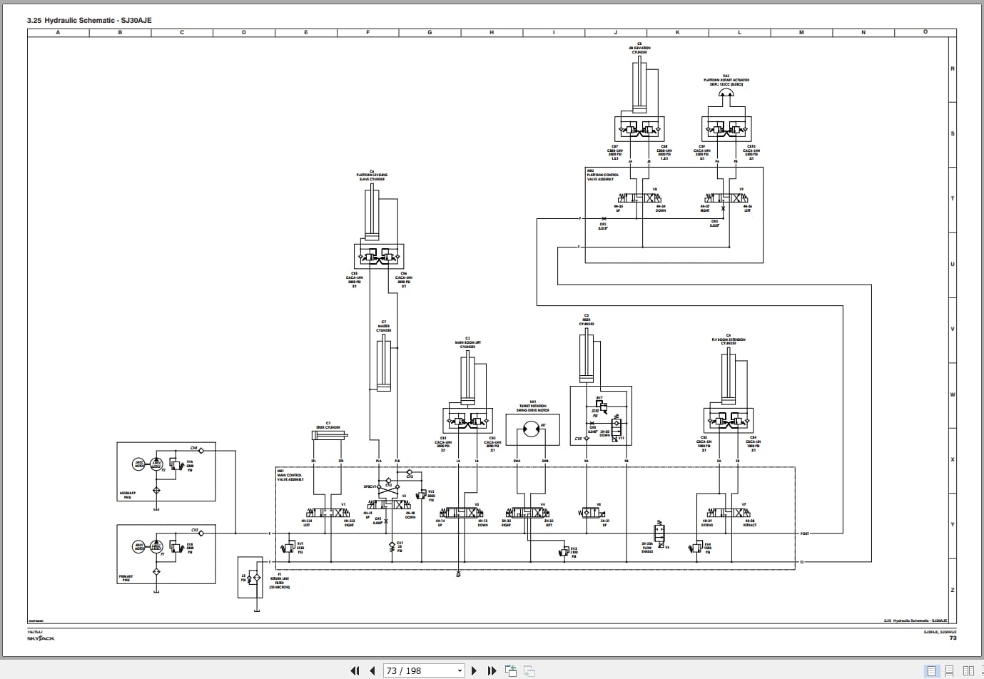
3.25 Hydraulic Schematic – SJ30AJE
3.26 Hydraulic Schematic – SJ30ARJE
3.27 Platform Controls Schematic – SJ30AJE ANSI/CSA
3.28 Platform Controls Schematic – SJ30ARJE ANSI/CSA, CE & AS
3.29 Platform Controls Schematic – SJ30ARJE KC
3.30 Base Controls Schematic – SJ30AJE ANSI/CSA
3.31 Base Controls Schematic – SJ30ARJE ANSI/CSA & AS
3.32 Base Controls Schematic – SJ30ARJE CE
3.33 Base Controls Schematic – SJ30ARJE KC
3.34 Electrical Schematic – ANSI/CSA
3.35 Electrical Schematic – CE
3.36 Electrical Schematic – AS
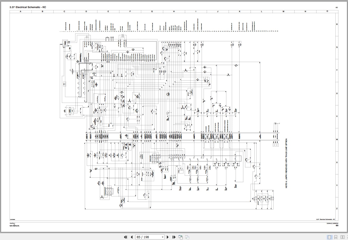
3.37 Electrical Schematic – KC
3.38 Motor Controller Electrical Schematic
Section 4 – Troubleshooting Information
4.1 Introduction
4.2 Electrical System
4.3 Hydraulic System
4.4 Load Sensing System
Section 5 – Procedures
5.1 General
5.2 Platform
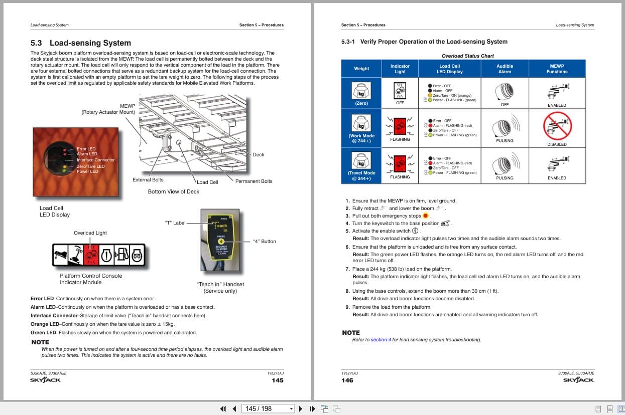
5.3 Load-sensing System
5.4 Boom & Jib
5.5 Turret
5.6 Base
5.7 Grease Points


