
0 ITEMSVIEW CART

-
VMware Mercury EPC Marine EU NA 06.2026 Q2.2026 Spare Parts Catalog
200 USDVMware Included:1/ Mercury Marine Europe EPC Q2 06.2026 Spare Parts Catalog VMWARE2/ Mercury Marine North America EPC Q2 06.2026 Spare Parts Catalog VMWARESize: You need to prepare 100GB fof ree space for installationInterface + Database Languages: English, Hungarian, Dutch, Danish, Spanish, Italian, German, Polish, Turkish, French, Czech, SwedishType of Program: Spare parts catalogVMware OS: Windows 7 32bit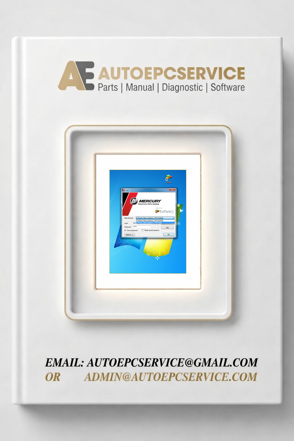
REALEASE :
REALEASE :
-
Kohler KIRA 2.8 Diagnostic Program High Level
Price range: 300 through 1,000 USDSize: You need to prepare 20 GB of free space for the best installationType of Program: Diagnostic Solution for Kohler EnginesInterface Language: English, Deutsch, French, Italian, Spanish, Portuguese, Russian, ChineseDatabase Language: EnglishRecommend OS: Windows 10, Windows 11Adapters:VCI DIAG4 KOHLERCable Deutsch, Cable EOBD/OBD2
REALEASE :
REALEASE :
-
Kohler KIRA 2.7.0.1 Diagnostic Program High Level
Price range: 250 through 900 USDSize: You need to prepare 20 GB of free space for the best installationType of Program: Diagnostic Solution for Kohler EnginesInterface Language: English, Deutsch, French, Italian, Spanish, Portuguese, Russian, ChineseDatabase Language: EnglishRecommendOS: Windows 10, Windows 11Version 2.7.0.1 Database 28.0Adapters:VCI DIAG4 KOHLERCable Deutsch, Cable EOBD/OBD2REALEASE :
REALEASE :
-
Hyster Yale CCS NCEA Software Updater FST 1.91 10.2024 Database Collection Program
Price range: 170 through 300 USDSize: You need to prepare 1GB of free space for the best installationType of program: .xml .hex .asc programRecommend OS: Windows 7, Windows 8, Windows 10, Windows 11 64bit (Tested on Windows 10 Pro 22H2 64-bit English)NOTE: “STILL DO NOT HAVE ALL THE DATABASE”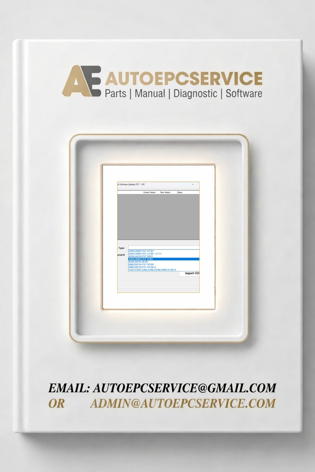
REALEASE :
REALEASE :
-
PSI PowerLink 2.3.1 Program Remote
150 USDManufacturer: Power Solutions International (PSI), developed with Noregon Systems, Inc.Product Name: PSI PowerLink Diagnostic SoftwareInterface + Database Languages: EnglishReccomend OS: Windows 10 (64-bit), Windows 11 (64-bit)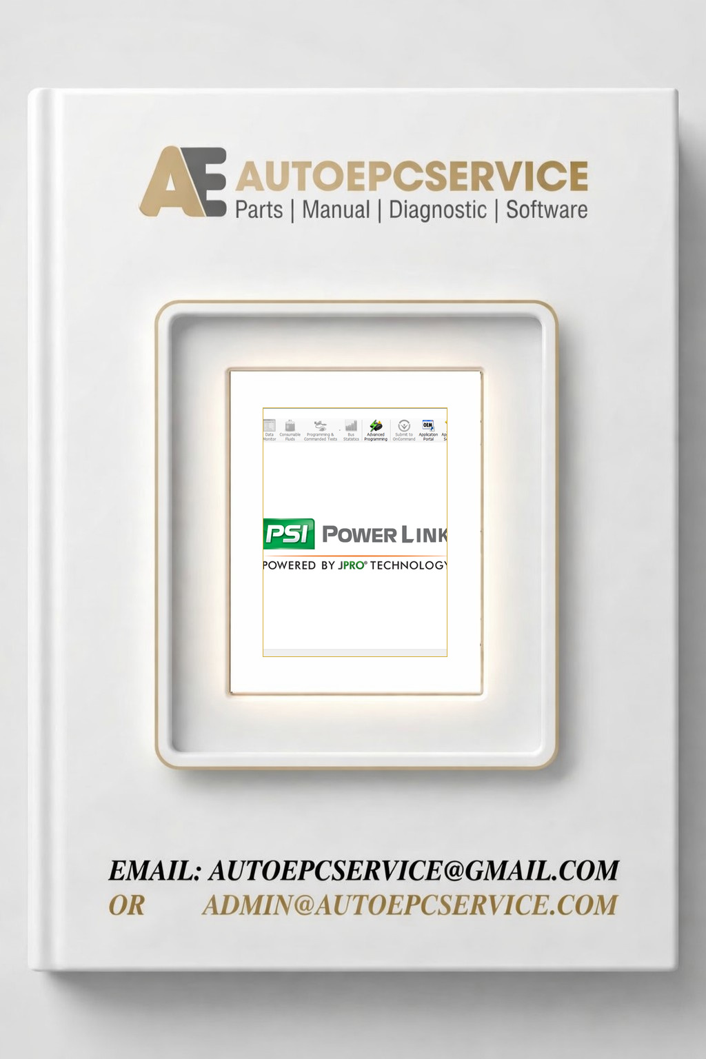
REALEASE :
REALEASE :
-
Yale One Soucre Client 06.2026 Schematic Trouble Shooting Codes
Price range: 100 through 250 USDSize: You need to prepare 10 GB of free space for installationManufacturer: YaleInterface Database Languages: Only EnglishType of Program: Diagnostic SoftwareType of vehicle: ForkliftOS: Windows 10, Window 11 64bit, (Tested on window 10 pro 22h2 64bit)
REALEASE :
REALEASE :
-
Hyster One Soucre Client 06.2026 Schematic Trouble Shooting Codes
Price range: 100 through 250 USDSize: You need to prepare 10GB of free space for installationManufacturer: HysterInterface Database Languages: Only EnglishType of Program: Diagnostic SoftwareType of vehicle: ForkliftOS: Windows 10, Window 11 64bit, (Tested on window 10 pro 22h2 64bit)
REALEASE :
REALEASE :
-
VMware Bourgault 04.2026 Parts Catalog Instructions Documentation Program
150 USDSize: You need to prepare 70 GB of free space for the best installationInterface Language: English (United States)Document Language: EnglishInstallation: Multiple PCsType of Program: Instruction Parts, Parts Book, Owner’s ManualManufacturer: BourgaultVMware OS: Windows 10 Pro 22h22 64bit
REALEASE :
REALEASE :
-
VMWARE Tigercat EPC 06.2026 Parts Catalog Service Operator Manuals
300 USDSize: You need to prepare 200gb free space for installationInterface Languages: English, RussianDatabase Language: EnglishType of program: VMWARE of Tigercat 06.2025 EPC Parts Catalog, Operators Manual, Service Manual & Miscellaneous DocumentsVMware OS: Win7
REALEASE :
REALEASE :
-
MAN MANTIS EPC v827 05.2026 Spare Parts Catalog Program
Price range: 70 through 150 USDSize: You need to prepare 30gb free space in disk C for installationInterface + Database Languages: Cestina, Dansk, Deutsch, English, Español, Francais, Hrvatski, etc (you can refer to pictures below)Type of program: Electronic part catalog of MANTISOS: Windows 10, 11 Pro 64-bit (Tested on Windows 10 pro 22h2 64bit english version)Developer: Lexcom Developer
REALEASE :
REALEASE :
-
Claas EPC Parts Doc 2.2 05.2026 933 Spare Parts Catalog
Price range: 90 through 200 USDSize: You need to prepare 150gb free space for installationInterface Languages: English, Hungarian, Dutch, Danish, Spanish, Italian, Mexican, German, Norwegian, Polish, Russian, Turkish, French, Czech, Netherlands, Swedish, Zhongwen, Magyar, Ellinika, Svenska, Suomi, Norsk, DanskaDatabase Languages: English, Italian, Spanish, German, French, Polish, RussianType of Program: Spare parts catalog for CLAAS AgriculturalType of vehicle: AgriculturalOS: Windows 7, Windows 8, Windows 10 32 & 64-bit (Tested on Windows 10 Pro 22h2 64bit English)Manufacturer: ClaasMACHINE CONFIGURATION FIX:” NEED TO PAY FOR ADDITIONAL”
REALEASE :
REALEASE :
-
John Deere EPC PA 05.2026 Spare Parts Catalog Program
Price range: 90 through 150 USDSize: You need to prepare 300gb free space for installationType of Program: Spare Parts Catalog JOHN DEERE AGRICULTURE, JOHN DEERE CONSTRUCTION, JOHN DEERE FORESTRYManufacturer: John DeereInterface Languages: Multiple (English, Hungarian, Dutch, Danish, Spanish, Italian, Mexican, German, Norwegian, Polish, Turkish, French, Czech, Swedish…etc..)Database Languages: Deutsch, Eesti, English, Espanol, Francais…etc (You can see so clearly in the pictures below)OS: Window 7 32 & 64bit, Window 8, Window 10 32 & 64bit (Tested on window 10 pro 22h2 64bit english)
REALEASE :
REALEASE :
-
Manitou EST 2025B Diagnostic Program Remote
350 USDSize: You need to prepare 20GB of free space for the best installationRecommended OS: Windows 10, Windows 11 32 & 64-bit (Tested on Windows 10 Pro 22H2 64-bit English)Interface + Database Language: EnglishHot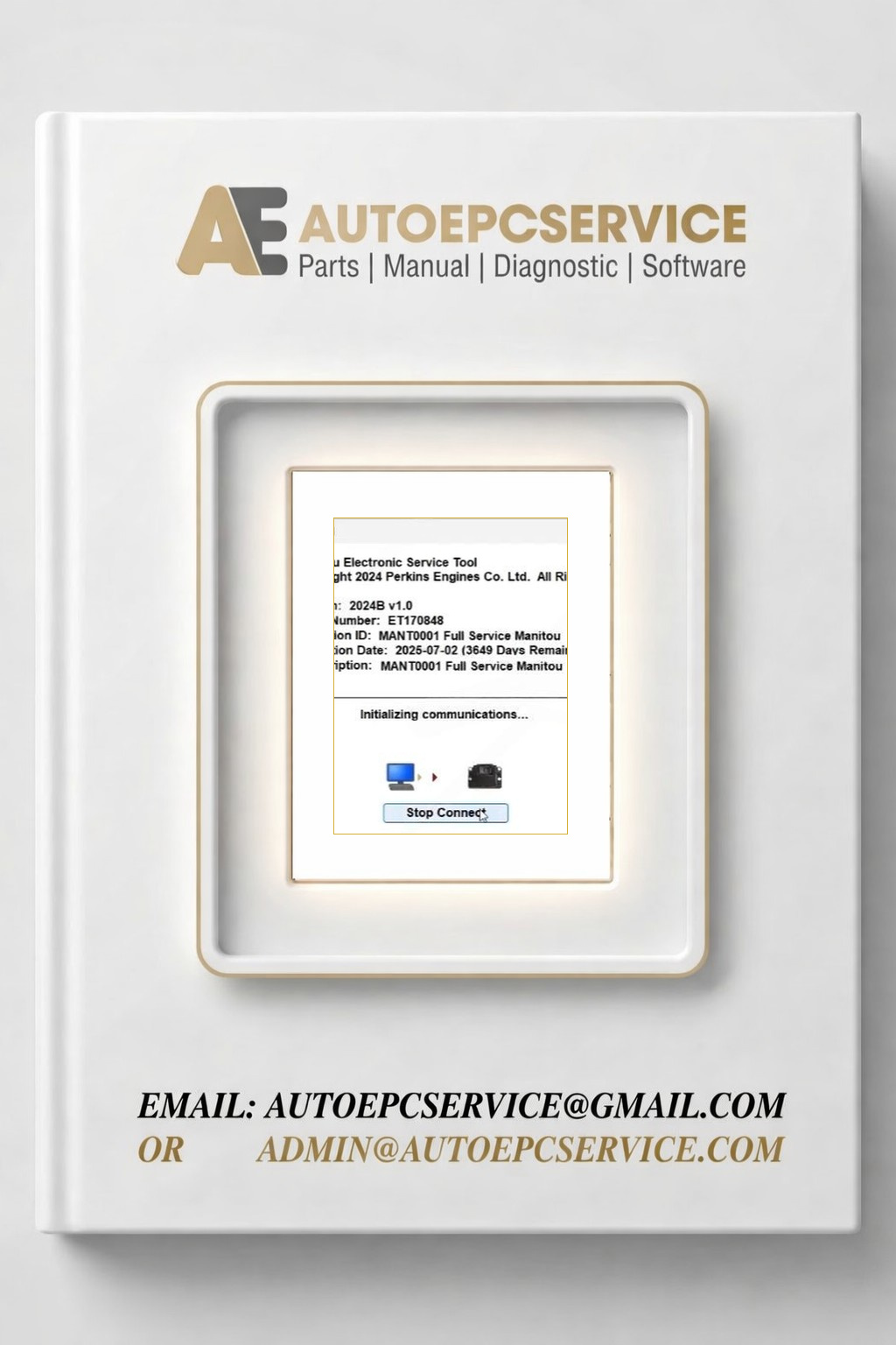
REALEASE :
REALEASE :
-
JPRO Commercial Vehicle 2026 v1.1 Diagnostic Program Remote
100 USDSize: You need to prepare 10 GB of free space on disk C for installationRecommend OS: Windows 10, 11 32 64 bit (Tested on Windows 10, 11 Pro 64 bit)How To Install by Remote1. Download Setup.2. Remote install the software via TeamViewer, AnyDesk3. If need do install + active full contact us
REALEASE :
REALEASE :
-
CAT ET Perkins EST 2026a Diagnostic Program Remote Combo
170 USDThe combo included:Size: You need to prepare 5GB of free space for installationRecommend OS: Windows 10, Windows 11 32 & 64bit (Tested on Windows 10 Pro 22H2 64bit english)Hot
REALEASE :
REALEASE :
-
PERKINS EST 2026a Diagnostic Program Remote
120 USDSize: You need to prepare 5GB of free space for installationRecommend OS: Windows 7, Windows 8, Windows 10, Windows 11 32 & 64bit (Tested on Windows 10 Pro 22H2 64bit)HotREALEASE :
REALEASE :
-
Hyundai Doosan DL0608 T4F DPF v0130 04.2026 Diagnostic Program Remote
120 USDSize: You need to prepare 1GB of free space for the best installation Manufacturer: Doosan Bobcat Hyundai Database Language: English Interface Language: English, Korean OS: Windows 10 or Windows 11 Pro x64 (Tested on window 10 pro 22h2 64bit english) Level: – Developer – Supervisor – Service
REALEASE :
REALEASE :
-
Doosan G2 Scan ECU 02.20 04.2026 Diagnostic Program Remote
120 USDSize: You need to prepare 1GB of free space for the best installation Manufacturer: Bobcat Database Language: English Interface Language: English, Korean OS: Windows 10 or Windows 11 Pro x64 (Tested on window 10 pro 22h2 64bit english) Level: – Developer – Supervisor – Service
REALEASE :
REALEASE :
-
Doosan G2 Scan DCU 03.20 04.2026 Diagnostic Program Remote
120 USDSize: You need to prepare 1GB of free space for the best installation Manufacturer: Bobcat Database Language: English Interface Language: English, Korean OS: Windows 10 or Windows 11 Pro x64 (Tested on window 10 pro 22h2 64bit english) Level: – Developer – Supervisor – Service
REALEASE :
REALEASE :
-
Bobcat Engine Analyzer 02.20 ECU 04.2026 Diagnostic Program Remote
150 USDSize: You need to prepare 1GB of free space for the best installationManufacturer: BobcatDatabase Language: EnglishInterface Language: English, KoreanOS: Windows 10 or Windows 11 Pro x64 (Tested on window 10 pro 22h2 64bit english)Level:– Developer– Supervisor– Service
REALEASE :
REALEASE :
-
Bobcat Engine Analyzer 03.20 DCU 04.2026 Diagnostic Program Remote
150 USDSize: You need to prepare 1GB of free space for the best installationBrand: BobcatDatabase Language: EnglishInterface Language: English, KoreanOS: Windows 10 or Windows 11 Pro x64Level:– Developer– Supervisor– Service
REALEASE :
REALEASE :
-
PALDIAG.NET 2020 Diagnostic Program Remote
180 USDSize: You need to prepare 20 GB of free space on disk C for the best installationType of program: Diagnostic Software for PALFINGER ProductsType of vehicle: Heavy EquipmentInterface Languages: English, Italian, Russian, Polish, Spanish, French, Portuguese, German, Dutch, Danish.Database Language: EnglishOS: Windows 10 Pro 22H2 is the best (Tested)Hot
REALEASE :
REALEASE :
-
ALL EPC Online Automotive Spare Parts Catalog Program
USDTHE COMBO INCLUDED:1/ Toyota EPC Online Parts Catalog 20262/ ISUZU EQ-Hit EPC Online Parts Catalog 20263/ HONDA EPC Online Parts Catalog 20264/ DAF EPC Online Parts Catalog 20265/ Mercedes Benz CAR Epc Online Parts Catalog 20266/ Renault Parts EPC Online Parts Catalog 20267/ Acura EPC Online Parts Catalog 20268/ BMW ETK EPC Online Parts Catalog 20269/ Changan EPC Online Parts Catalog 202610/ MG SAIC Motor EPC Online Parts Catalog 202611/ Hyundai Snap-on EPC Online Parts Catalog 202612/ Genesis WPC MOBIS EPC Online Parts Catalog 202613/ Hyundai WPC MOBIS EPC Online Parts Catalog 202614/ KIA WPC MOBIS EPC Online Parts Catalog 202615/ Genesis WPC MOBIS EPC Online Parts Catalog 202616/ Land Rover JLR EPC Online Parts Catalog 202617/ Land Rover JLR EPC Online Parts Catalog 202618/ Jaguar JLR EPC Online Parts Catalog 202619/ Toyota Parts catalog online 202620/ Lexus Dealer EPC Online Parts Catalog 202621/ Mercedes-Benz Daimler Truck EPC Online Parts Catalog 202622/ Peugeot PSA Service Box EPC Online Parts Catalog VIN Search 202623/ Mitsubishi FUSO ASCENT EPC Online Parts Catalog 202624/ Peugeot (PSA) Service Box EPC Online Parts Catalog 202625/ Mopar FCA EPC Online Parts Catalog VIN Search 202626/ Chrysler FCA EPC Online Parts Catalog 202627/ Mopar FCA EPC Online Parts Catalog 202628/ DODGE FCA EPC Online Parts Catalog 202629/ Suzuki Snap-on EPC Online Parts Catalog 2026REALEASE :
-
YANMAR Marine Industrial Engine EPC 2026 Spare Part Catalog Program Remote
300 USDSize: You need to prepare 200GB of free space for installationInterface Languages & Database Languages: Only EnglishType of Program: Spare Part Catalog for YANMARType of vehicle: Marine & Industrial EngineRecommend OS: Windows 10, Windows 11 32 & 64bit (Tested on window 10 pro 22h2 64bit english)Hot
REALEASE :
REALEASE :

-
Changan Automotive 3.09 GB PDF Service Manual Wiring Diagram
100 USDSize: 3.09 GBFormat: PDFLanguage: EnglishBrand: Chana, ChanganType of Machine: AutomotiveType of Manual: Service Manual, Wiring Diagram, Workshop Manual, Electric DiagramHot
REALEASE :
REALEASE :
-
Lifan Car 1.8 GB PDF User Service Manual Parts Catalog
150 USDSize: 1.82 GBFormat: PDF, XLSLanguage: English, ChineseBrand: LifanType of Machine: AutomotiveType of Manual: Wiring Diagram, Service Manual, Owner’s Manual, User Manual, Parts CatalogHot
REALEASE :
REALEASE :
-
Hustler 9.16 GB Mowers Collection Full Manuals PDF Updated 2026
300 USDSize: 9.16 GBLanguage: EnglishFormat: PDFBrand: HustlerType of Machine: MowersType of Manual: Instructions Manual, Assembly Kit Manual, Interactive Parts Book, Operators Manual, Parts Manual, Service Manual, Owners ManualUpdated 2026Hot
REALEASE :
REALEASE :
-
Tennant Machine 5.58 GB PDF Instruction Operator Parts Manuals 2026
100 USDSize: 5.58 GBFormat: PDFLanguage: EnglishBrand: TennantType of Machine: Burnishers & Floor Machines, Extractors, Hardware, Robotics, ScrubbersType of Manual: Instruction Bulletin, Operator Manuals, Parts ManualsUpdate 2026
REALEASE :
REALEASE :
-
Doosan Bobcat Forklift Service Manual PDF Request
USD1. How to Request Support:– Contact us directly via WhatsApp, Telegram, or Email => CLICK HERE2. Please provide the following information:– Machine nameplate …– Model: [Enter your forklift model]– Serial number: [Enter your serial number]Example request:– Model: D70S-9– Serial Number: FDB21-5105-00048Note: To ensure accurate and effective support, please make sure the information you provide is correct.REALEASE :
-
Gradall Industries 11 GB PDF Service Operator Technical Parts Manual Update 2026
150 USDSize: 11 GBFormat: PDFLanguage: EnglishBrand: GradallType of Machine: Crawler Undercarriage, Excavator, Rough Terain WheeledType of Document: Illustrated Parts Manual , Service Manuals, Operator Manual, Hydraulic Diagram, Electrical Diagram, Technical ManualUpdate: 2026Hot
REALEASE :
REALEASE :
-
Snorkel Lifts Schematics Service Parts Operators Manual PDF 15.5 GB
150 USDSize: 15.5 GBFormat: PDFLanguage: EnglishBrand: SnorkelType of Machine: Lifts, Boom Lifts, Material Lift, Telehandler, Rough Terrain Scissor LiftType of Document: Service Manual, Parts Manual, Electrical Schematic, Hydraulic Schematic, Operators Manual, Troubleshooting Manual, Maintenance ManualHot
REALEASE :
REALEASE :
-
UpRight Lifts Service Parts Operator Manuals PDF 2.80 GB
150 USDSize: 2.80 GBFormat: PDFLanguage: English, Dutch, French, German, Italian, SpanishBrand: UpRightType of Machine: Heavy Equipment, Scissor Lift, Work Platform, Portable Personnel Lift, LiftsType of Document: Part Manual, Service Manuals, Operator Manual, Hydraulic Diagram, Electrical DiagramHot
REALEASE :
REALEASE :
-
Manitou Telescopic Handlers MHT MHT-X Series Service Operator Part Manual Update 2024
1,000 USDSite: 34.8 GBFormat: PDFLanguage: English, some FrenchBrand: ManitouType of Machine : TelehandlerType of Document: Service Manual,Repair Manual, Operator Manuals, Part ManualModel: MLT Series, MLT-X SeriesUpdate: 2024Hot
REALEASE :
REALEASE :
-
Manitou Telehandler MLA MLA-T Series Service Operator Part Manual Update 2024
250 USDSite: 2.36 GBFormat: PDFLanguage: English, some FrenchBrand: ManitouType of Machine : TelehandlerType of Document: Service Manual,Repair Manual, Operator Manuals, Part ManualModel: MLA Series, MLA-T SeriesUpdate: 2024Hot
REALEASE :
REALEASE :
-
Manitou Forklift M M-X Series Service Operator Part Manual Update 2024
250 USDSite: 2.51 GBFormat: PDFLanguage: English, some FrenchBrand: ManitouType of Machine : ForkliftType of Document: Service Manual,Repair Manual, Operator Manuals, Part ManualModel: M Series, M-X SeriesUpdate: 2024Hot
REALEASE :
REALEASE :
-
Manitou Telehandler MHT MHT-X Series Service Operator Part Manual Update 2024
500 USDSite: 15 GBFormat: PDFLanguage: English, some FrenchBrand: ManitouType of Machine : TelehandlerType of Document: Service Manual,Repair Manual, Operator Manuals, Part ManualModel: MHT Series, MHT-X SeriesUpdate: 2024Hot
REALEASE :
REALEASE :
