
0 ITEMSVIEW CART

✓
Expert Support
✓
Full Speed
✓
100% Working
Ausa Taurulift T306H T307H Operation Manual
Size: 6.79 MB
Format: PDF
Language: English
Brand: Ausa
Type of Machine: Taurulift
Type of Manual: Operation Manual, Electric and Hydraulic Diagrams
Model: Ausa T306H T307H Taurulift
above chassis number 33268001
Number of Pages: 154 Pages
20 USD
- Description
Description
Contents:
1 General Information
1.1 How to identify your machine
1.1.1 Machine directions
1.1.2 Warning plates and labels on the machine
1.1.3 Symbols used on the machine
1.2 How to identify the machine
1.2.1 Model and type
1.2.2 Manufacturer
1.2.3 Identification plates
1.2.4 Ec marking
1.2.5 Frame number
1.2.6 Engine serial number
1.3 Acceptable use
1.3.1 Acceptable use
1.3.2 Unacceptable use
1.3.3 Operator risks
1.3.4 Applicable standards
1.3.5 Safety devices
1.4 General description
1.4.1 Main parts
1.4.2 Description of the main parts
1.4.3 Optional accessories
1.5 Technical data
1.5.1 Diesel engine
1.5.2 Transmission
1.5.3 Steering
1.5.4 Brakes
1.5.5 Standard tyres
1.5.6 Service temperature
1.5.7 Hydraulic circuit
1.5.8 Capacity/dimensions
1.5.9 Forks
1.5.10 Electrical equipment
1.5.11 Vibration and noise levels
1.5.12 Forklift measurements
1.6 Duration of use
1.7 Accessories included
1.7.1 Documentation provided2 Special safety messages
2.1 General information
2.2 Prerequisites for personnel
2.2.1 Prerequisites for operators
2.2.2 Prerequisites for personnel in charge of maintenance
2.2.3 Work and maintenance clothing
2.2.4 Personal protection equipment
2.3 Safety standards
2.3.1 Working area
2.3.2 Prior preparation
2.3.3 During work and maintenance
2.3.4 Parking the forklift and stopping the engine
2.4 Safety devices
2.5 Overload system3 Operating instructions
3.1 Before entering the machine
3.2 Accessing the machine
3.2.1 Accessing the cab
3.2.1.1 Exiting the cab in an emergency situation (if fitted)
3.2.2 Adjusting the seat
3.2.3 Adjusting the seat belt
3.2.4 Adjusting the rear view mirrors
3.2.5 Use of the courtesy light (if fitted)
3.3 Control panel
3.3.1 Controls
3.3.2 Engine controls
3.3.2.1 Starter switch
3.3.2.2 Forward/reverse selector
3.3.2.3 Back-up alarm and speed selector
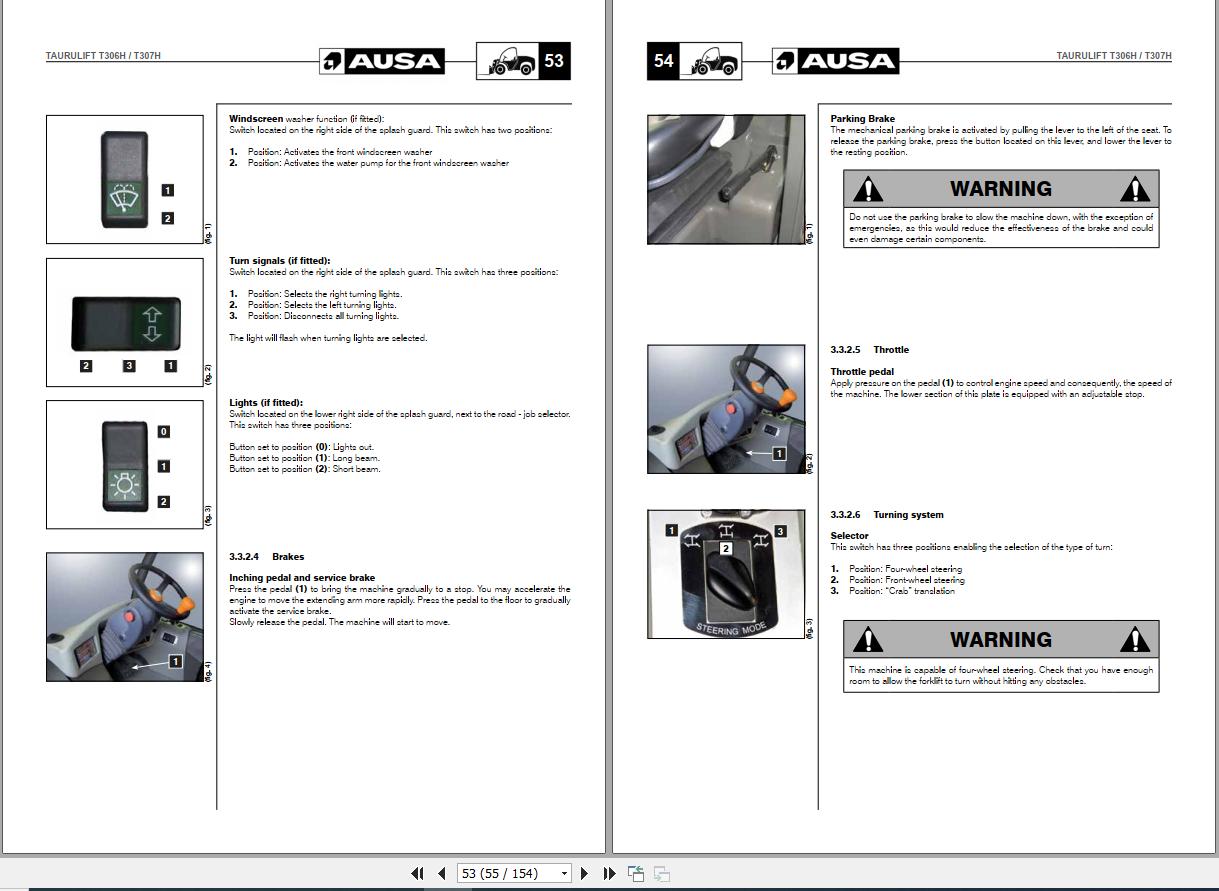
3.3.2.4 Brakes
3.3.2.5 Throttle
3.3.2.6 Turning system
3.3.2.7 Road – job site switch
3.3.2.8 Auxiliary driving controls
3.3.2.8.1 Rotating beacon
3.3.2.8.2 Hazard warning lights (if fitted)
3.3.2.8.3 Job lights (if fitted)
3.3.2.8.4 Continuous and high flow switch (if fitted)
3.3.2.8.5 Fan speed regulator (if fitted)
3.3.2.8.6 Hot air temperature regulator (if fitted)
3.3.2.8.7 Air conditioning (if fitted)
3.3.3 Gauges and indicators
3.3.3.1 Gauges
3.3.3.2 Indicators
3.3.4 Joystick
3.3.4.1 Selection of movements
3.3.4.1.1 Standard machine
3.3.4.1.2 Inverse controls (optional)
3.3.4.2 Emergency stop
3.3.4.2.1 Deactivation of the overload system
3.3.4.3 lifting/lowering of the extending arm
3.3.4.4 Forward/back tilt of the fork carriage
3.3.4.4.1 Standard machine
3.3.4.4.2 Inverse controls (optional)
3.3.4.5 Extension/retraction of the extending arm
3.3.4.5.1 Standard machine
3.3.4.5.2 Inverse controls (optional)
3.3.4.6 Auxiliaries hydraulic take-off (if fitted)
3.3.4.6.1 4th valve
3.3.4.6.2 5th valve (if fitted)
3.3.4.7 Attachment of tools
3.4 Start-up
3.4.1 Before starting the engine
3.4.1.1 Machine start-up check list
3.4.2 Start-up
3.4.3 Start the engine using an external source
3.4.4 Start up at low temperatures
3.4.5 Disconnecting the battery
3.4.6 Start-up of the machine
3.4.7 Parking the forklift and cutting the engine
3.5 Use of the forklift
3.5.1 Machine nominal load
3.5.1.1 Load Centre (fig. 1)
3.5.1.2 Load Capacity
3.5.2 Use of the load chart
3.5.2.1 Load charts (except USA and Australia)
3.5.2.2 Load charts (USA market)
3.5.2.3 Load charts (Australian market)
3.5.3 Overload system
3.5.3.1 Overload system calibration procedure.
3.5.3.1.1 Standard machines
3.5.3.1.2 Standard for Australian market (optional)
3.5.3.2 Usage
3.5.3.2.1 Standard machines
3.5.3.2.2 Standard for Australian market (optional)
3.5.4 Handling loads
3.5.4.1 Adjustment of forks
3.5.4.2 Working phases
3.5.5 Replacement of tools
3.5.6 Transporting towed loads
3.6 Transporting the machine
3.6.1 Towing a damaged machine
3.6.2 Transfer by road and jobs
3.6.3 Loading the machine with a crane
3.6.4 Transport on another vehicle
3.6.5 Parking and non-operational machines
3.6.5.1 Short stops
3.6.5.2 Extended stops
3.6.6 Cleaning and washing the machine
3.6.6.1 Cleaning instructions
3.6.6.2 Washing the machine
3.6.7 Elimination
3.6.7.1 Elimination of batteries4 Periodic maintenance operations
4.1 Lubricants, Safety and Hygiene standards
4.2 Scheduled maintenance
4.2.1 Lubrication and maintenance chart
4.3 Maintenance operations
4.3.1 Disconnecting the battery
4.3.2 Access to engine, cab and tank compartments
4.3.3 Supply circuit
4.3.4 Grease
4.3.5 Tyres and wheels
4.3.6 Brakes
4.3.6.1 Brake oil level
4.3.7 Engine air filter
4.3.8 Cab air filter
4.3.9 Engine coolant circuit
4.3.10 Tank oil level
4.3.10.1 Replacing hydraulic fluid
4.3.10.2 Suction oil filter
4.3.11 Replacement of the hydrostatic transmission filter element
4.3.11.1 Hydrostatic transmission filter
4.3.11.2 Regulation of the pressure regulation valves in the hydraulic circuit (fig. 1, 2)
4.3.11.3 Hydraulic hoses
4.3.12 Transfer box and differential oil level
4.3.12.1 Front and rear differential
4.3.12.2 Transfer box
4.3.13 Reduction gear oil level (front and rear)
4.3.14 Re-adjustment of the longitudinal axis of the wheels
4.3.15 Regulation of clearance for the arm section guides
4.3.16 Checking safety devices
4.3.17 Engine oil
4.3.17.1 Engine oil level
4.3.17.2 Changing the oil and the oil filter
4.3.18 Alternator belt
4.4 Electric installation
4.4.1 Battery
4.4.2 Fuses – relays
4.4.3 12 v supply lamps
4.5 Liquids and lubricants
4.5.1 Refuelling
4.5.2 Product details
4.5.2.1 Engine oil
4.5.2.2 Lubricants, oils and filter cartridges
4.5.2.3 Fuel
4.5.2.4 Greases
4.5.2.5 Brakes & Inching5 Diagrams
and charts
5.1 Screw torques
5.2 Forklift actuation hydraulic diagram
5.2.1 Standard machines and Inverse controls machines (optional)
5.2.2 Continuous and high flow machines
5.3 Extending arm hydraulic diagram
5.4 Transmission hydraulic diagram
5.4.1 T306H 2 speeds
5.4.2 T306H / T307H 1 speed
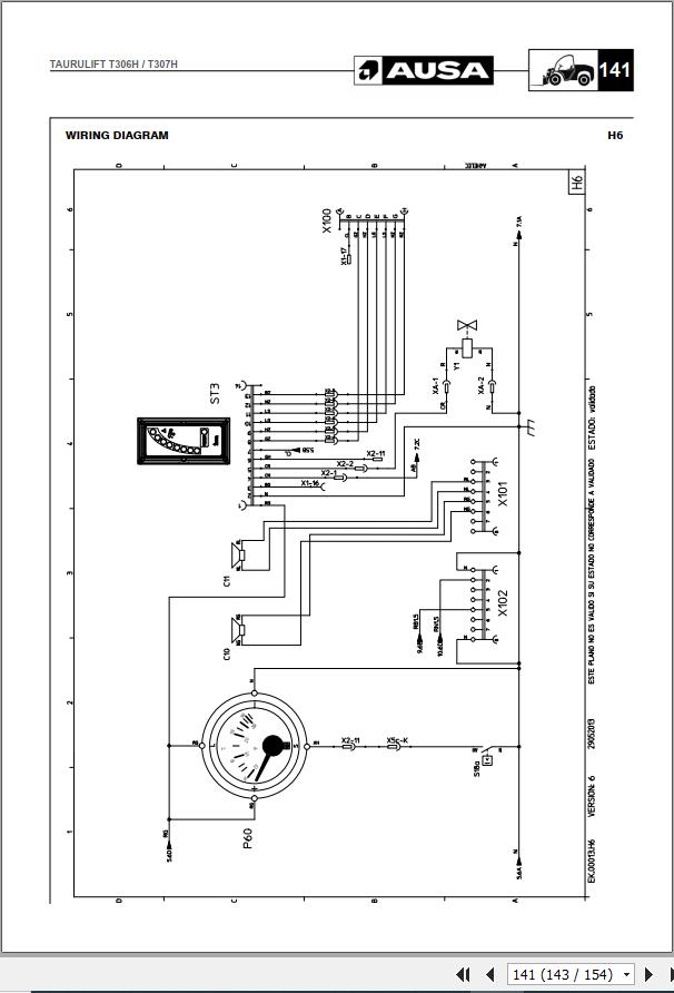
5.5 Wiring diagram
5.6 Identification of failures in hydrostatic transmissions6 Ec certificate of conformity
Related Products
-
Ausa Taurulift T 133 H X2 Parts Manual
20 USDSize: 3.94 MBFormat: PDFLanguage: EnglishBrand: AusaType of Machine: TauruliftType of Manual: Parts ManualModel: Ausa T 133 H X2 TauruliftNumber of Pages: 134 Pages
REALEASE :
REALEASE :
-
Ausa Taurulift T306H Parts Manual
20 USDSize: 5.79 MBFormat: PDFLanguage: EnglishBrand: AusaType of Machine: Taurulift (Telehandler)Type of Manual: Parts ManualModel: Ausa T306H TauruliftNumber of Pages: 155 Pages
REALEASE :
REALEASE :
-
Ausa Taurulift T307H Parts Manual
20 USDSize: 5.95 MBFormat: PDFLanguage: EnglishBrand: AusaType of Machine: Taurulift (Telehandler)Type of Manual: Parts ManualModel: Ausa T307H TauruliftNumber of Pages: 161 Pages
REALEASE :
REALEASE :
-
Ausa Forklift Models Parts Manual CD
Original price was: 30.20Current price is: 20. USDAusa Forklift Models Parts Manual CDSize: 156 MBFormat: PDFLanguage: ENType of document: Parts Catalog Models List: AUSA Forklift C11M Parts Manual.pdfAUSA Forklift C150H-C150HX4 Parts Manual.pdfAUSA Forklift C200Hx4 Parts Manual.pdfAUSA Forklift C250H Parts Manual.pdfAUSA Forklift C250HLE Parts Manual.pdfAUSA Forklift C250HX4 Parts Manual.pdfAUSA Forklift C250HX4LE Parts Manual.pdfAUSA Forklift C300H Parts Manual.pdfAUSA Forklift C300HX4 Parts Manual.pdfAUSA Forklift C350HX4 Parts Manual.pdfAUSA Forklift C400H Parts Manual.pdfAUSA Forklift C400HI Parts Manual.pdfAUSA Forklift C400HIx4 Parts Manual.pdfAUSA Forklift C400Hx4 Parts Manual.pdfAUSA Forklift C500H Parts Manual.pdfAUSA Forklift C500HIx4 Parts Manual.pdfAUSA Forklift C500Hx4 Parts Manual.pdfAUSA Forklift CE10 Parts Manual.pdfAUSA Forklift CE11 Parts Manual.pdfAUSA Forklift CE16 Parts Manual.pdfAUSA Forklift CE7 Parts Manual.pdfAUSA Forklift CH130-X4 CH150-X4 Parts Manual.pdfAUSA Forklift CH200 CH250 Parts Manual.pdfAUSA Forklift CHG150 CHG150x4 Parts Manual.pdfAUSA Forklift CM280 Parts Manual.pdfAUSA Forklift CS20 CT20 Parts Manual.pdfAUSA Forklift CSH25 CTH25 Parts Manual_Es.pdfAUSA Forklift CSH30 CTH30 Parts Manual_Es.pdfAUSA Forklift CV20 CV22 Parts Manual.pdfAUSA Forklift CV25 CVH25 Parts Manual.pdfAUSA Forklift CVH20 CH22 Parts Manual.pdfAUSA Forklift T204H Parts Manual.pdf-33%
REALEASE :
01.10.2020
REALEASE :
01.10.2020
-
Ausa Taurulift T276H Parts Manual
20 USDSize: 4.22 MBFormat: PDFLanguage: EnglishBrand: AusaType of Machine: Taurulift (Telehandler)Type of Manual: Parts ManualModel: Ausa T276H TauruliftNumber of Pages: 115 Pages
REALEASE :
REALEASE :
-
XCMG Full Collection Manuals DVD
Original price was: 50.30Current price is: 30. USDXCMG Full Collection Manuals DVDSize: 970 MBLanguage: English_Chinese_RU_ESBrand: XCMGFormat: pdfType of documents: Parts Catalog, Operation & Maintenance Manual, Operator’s Manual, Service Manual, Instruction ManualHigh-Speed Link DownloadHot-40%
REALEASE :
01.10.2020
REALEASE :
01.10.2020
-
Ausa Taurulift T 235 H Parts Manual
20 USDSize: 4.60 MBFormat: PDFLanguage: EnglishBrand: AusaType of Machine: TauruliftType of Manual: Parts ManualModel: Ausa T 235 H TauruliftNumber of Pages: 169 Pages
REALEASE :
REALEASE :
-
Ausa Taurulift T 133 H X4 Parts Manual
20 USDSize: 4.43 MBFormat: PDFLanguage: EnglishBrand: AusaType of Machine: TauruliftType of Manual: Parts ManualModel: Ausa T 133 H X4 TauruliftNumber of Pages: 141 Pages
REALEASE :
REALEASE :