
0 ITEMSVIEW CART

✓
Expert Support
✓
Full Speed
✓
100% Working
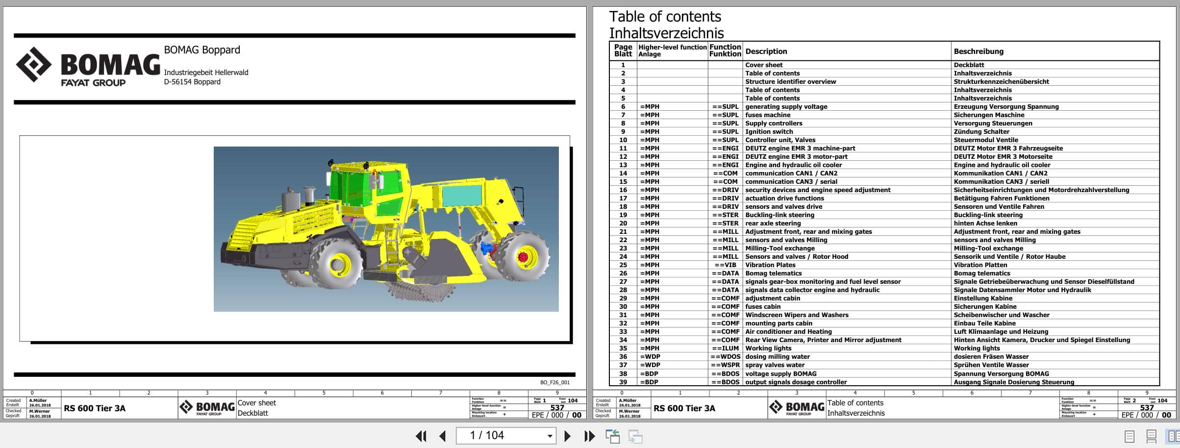
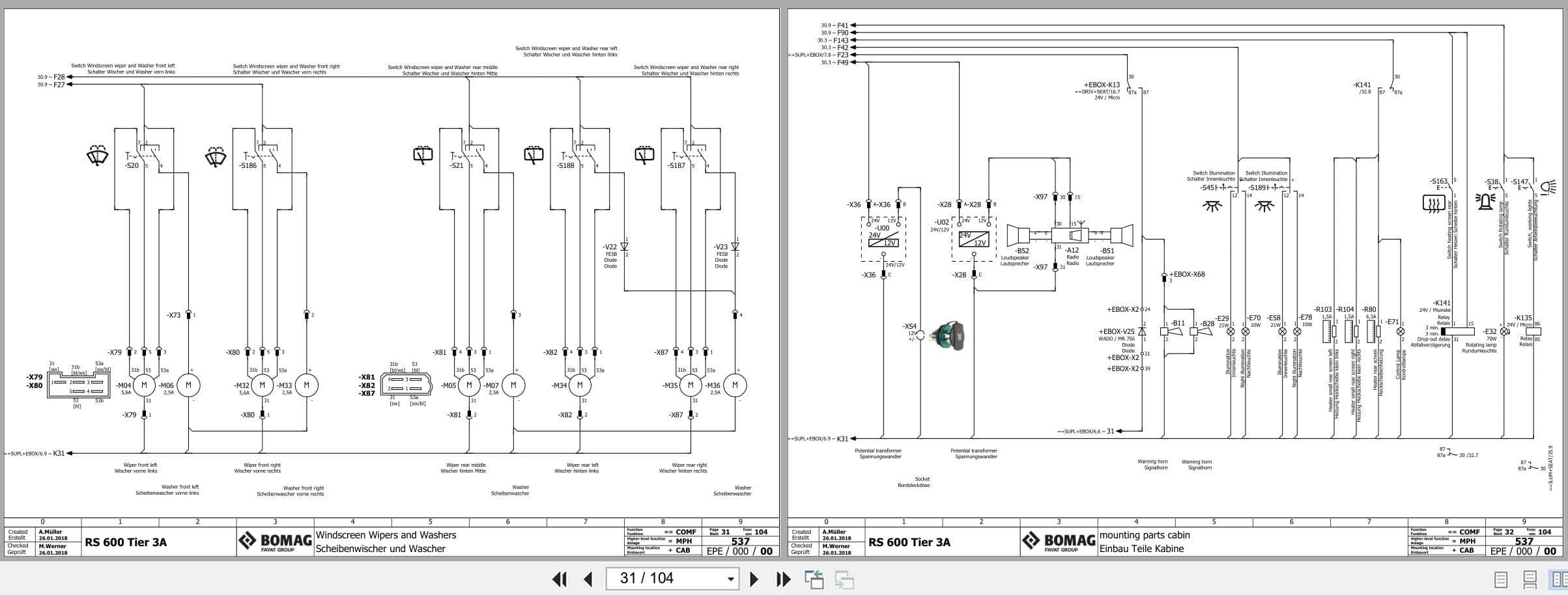
Bomag Soil Stabilizer – Asphalt Recycler RS 600 T3 Electrical Hydraulic Pneumatic Schematic
Size: 43.43 MB
Format: PDF
Language: English, German
Brand: Bomag
Type of Machine: Soil Stabilizer – Asphalt Recycler
Type of Manual: Electrical Schematic, Hydraulic Schematic, Pneumatic Schematic
Model: Bomag RS 600 T3 Soil Stabilizer – Asphalt Recycler
Serial Number: 101590351001 – 101590359999 (00825147)
30 USD
- Description
Description
List of Files:
Bomag Soil Stabilizer – Asphalt Recycler RS 600 T3 Electrical Hydraulic Pneumatic Schematic 101590351001 – 101590359999 (00825147)
000000000000000181_00_000.pdf
Doc1 Leading Documentation
Cover Sheet
Table Of Contents
Structure Identifier Overview
Efs Circuit Diagram
Mph Basic Machine
Wdp Water Dosage Plant (Option)
Emul Bitumen Emulsion Plant
Doc2 Reports And Drawings
System Overview – Emulsion Bitumen Plant
Component-Listing
Terminal Diagram
Pin Overview A66
Pin Overview A80
Pin Overview A81
Pin Overview S55
Pin Overview S71
Pin Overview A99
Pin Overview A83
Pin Overview A98
Plug Diagram
Illustration X1 – Fuses And Wago Relays
Illustration X2 – Frame Rear
Illustration X3 – Frame Front
Illustration X4 – Bitumen Plant
Overview E-Box
Assembly Plate Overview
000000000000000471_00_000.pdf
Doc1 Leading Documentation
Cover Sheet
Table Of Contents
Structure Identifier Overview
Table Of Contents
Efs Circuit Diagram
Mph Basic Machine
Wdp Water Dosage Plant (Option)
Bdp Bitumen Dosage Plant (Option)
Doc2 Reports And Drawings
Component-Listing
Terminal Diagram
Pin Overview A66
Pin Overview A80
Pin Overview A81
Pin Overview A145
Pin Overview S55
Pin Overview S71
Pin Overview A03
Pin Overview A99
Pin Overview A83
Pin Overview A98
Pin Overview A104
Plug Diagram
Illustrations Terminal Strips
Overview E-Box
Assembly Plate Overview
System Overview – Modules Bitumen Plant
000000000000000537_00_000.pdf
Doc1 Leading Documentation
Cover Sheet
Table Of Contents
Structure Identifier Overview
Table Of Contents
Efs Circuit Diagram
Mph Basic Machine
Wdp Water Dosage Plant (Option)
Bdp Bitumen Dosage Plant (Option)
Doc2 Reports And Drawings
Component-Listing
Illustrations Terminal Strips
Overview E-Box
Assembly Plate Overview
System Overview – Modules Bitumen Plant
Terminal Diagram
Pin Overview A66
Pin Overview A80
Pin Overview A81
Pin Overview A145
Pin Overview S55
Pin Overview S71
Pin Overview A03
Pin Overview A99
Pin Overview A83
Pin Overview A98
Pin Overview A104
Plug Diagram
000000000000000616_00_000.pdf
Cover sheet
Table of contents :1 – 11.h
Overview
Drive circuit
Milling circuit
Fan drive
Cylinder functions
W25, W26 Water dosing system
W27, W28 Water dosing system
BE23, BE24 foam bitumen system
BE25, BE26 Emulsion dosing plant
AG46 Water dosing system
Compressed air system + pilot control dosing beam
Tank
Pump transfer gear
Device tag list :A1 -A19
Device tag list : A20 F4
Device tag list :F5 – MP11
Device tag list :MP12 – MP29
Device tag list :P1 – PV4
Device tag list :PZ1 – V12
Device tag list :V13-
Device tag list :WFI – WV3
Device tag list :WV4-Z4
000000000000000808_00_000.pdf
Title Page – Cover Sheet
Table Of Contents : 1 – 24
Overview
Drive Circuit
Milling Circuit
Fan Drive
Cylinder Functions
W25, W26 Wasserdosieranlage W25, W26 Water Dosing System
W27, W28 Wasserdosieranlage W27, W28 Water Dosing System
Be23, Be24 Schaumbitumenanlage Be23, Be24 Foam Bitumen System
Be25, Be26 Emulsionsanlage Be25, Be26 Emulsion Sprinkler System
Ag46 Wasserdosieranlage + Rüttelplatte Ag46 Water Dosing System + Vibration Plate
Druckluftanlage + Vorsteuerung Dosierbalken Compressed Air System + Pilot Operation Dosing Valves
Tank
Pump Transfer Gear
Device Tag List : A1 – A19
Device Tag List : A20 – F4
Device Tag List : F5 – Mp11
Device Tag List : Mp12 – Mp29
Device Tag List : Mp30 – Pmp1
Device Tag List : Pp1 – V8
Device Tag List : V9 – V27
Device Tag List : V28 – Wv1
Device Tag List : Wv2 – Z5
000000000000000809_00_000.pdf
Title Page – Cover Sheet
Table Of Contents : 1 – 24
Overview
Drive Circuit
Milling Circuit
Fan Drive
Cylinder Functions
W25, W26 Wasserdosieranlage W25, W26 Water Dosing System
W27, W28 Wasserdosieranlage W27, W28 Water Dosing System
Be23, Be24 Schaumbitumenanlage Be23, Be24 Foam Bitumen System
Be25, Be26 Emulsionsanlage Be25, Be26 Emulsion Sprinkler System
Ag46 Wasserdosieranlage + Rüttelplatte Ag46 Water Dosing System + Vibration Plate
Druckluftanlage + Vorsteuerung Dosierbalken Compressed Air System + Pilot Operation Dosing Valves
Tank
Pump Transfer Gear
Device Tag List : A1 – A19
Device Tag List : A20 – F4
Device Tag List : F5 – Mp11
Device Tag List : Mp12 – Mp29
Device Tag List : Mp30 – Pmp1
Device Tag List : Pp1 – V8
Device Tag List : V9 – V27
Device Tag List : V28 – Wv1
Device Tag List : Wv2 – Z5
000000000000000840_00_000.pdf
Doc1 Leading Documentation
Cover Sheet
Table Of Contents
Structure Identifier Overview
Table Of Contents
Efs Circuit Diagram
Mph Basic Machine
Wdp Water Dosage Plant (Option)
Bdp Bitumen Dosage Plant (Option)
Doc2 Reports And Drawings
Component-Listing
Illustrations Terminal Strips
Overview E-Box
Assembly Plate Overview
System Overview – Modules Bitumen Plant
Component-Listing
Terminal Diagram
Pin Overview A66
Pin Overview A80
Pin Overview A81
Pin Overview A145
Pin Overview S55
Pin Overview S71
Pin Overview A03
Pin Overview A99
Pin Overview A83
Pin Overview A98
Pin Overview A104
Plug Diagram
000000000000000862_00_000.pdf
Doc1 Leading Documentation
Cover Sheet
Table Of Contents
Structure Identifier Overview
Table Of Contents
Efs Circuit Diagram
Mph Basic Machine
Wdp Water Dosage Plant (Option)
Bdp Bitumen Dosage Plant (Option)
Doc2 Reports And Drawings
Component-Listing
Illustrations Terminal Strips
Overview E-Box
Assembly Plate Overview
System Overview – Modules Bitumen Plant
Component-Listing
Terminal Diagram
Pin Overview A66
Pin Overview A80
Pin Overview A81
Pin Overview A145
Pin Overview S55
Pin Overview S71
Pin Overview A03
Pin Overview A99
Pin Overview A83
Pin Overview A98
Pin Overview A104
Plug Diagram
000000000059311000_01_000.pdf
000000000059330122_00_001.pdf
000000000059330122_02_002.pdf
000000000059330125_00_001.pdf
000000000059330125_00_002.pdf
Related Products
-
Bomag Roller BW211D-4 to BW216D-4 Service Training 00809999 2005
20 USDSize: 8.53 MBFormat: PDFLanguage: EnglishBrand: BomagType of Machine: Single Drum RollerType of Manual: Service Training, Hydraulic Diagram, Electric DiagramModel: Bomag Single Drum RollerBW 211 D-4, BW 213 D-4, BW 216 D-4 With Deutz Engine 2012 Und 1013ECPart Number: 00809999Publication Date: 2005Number of Pages: 145 Pages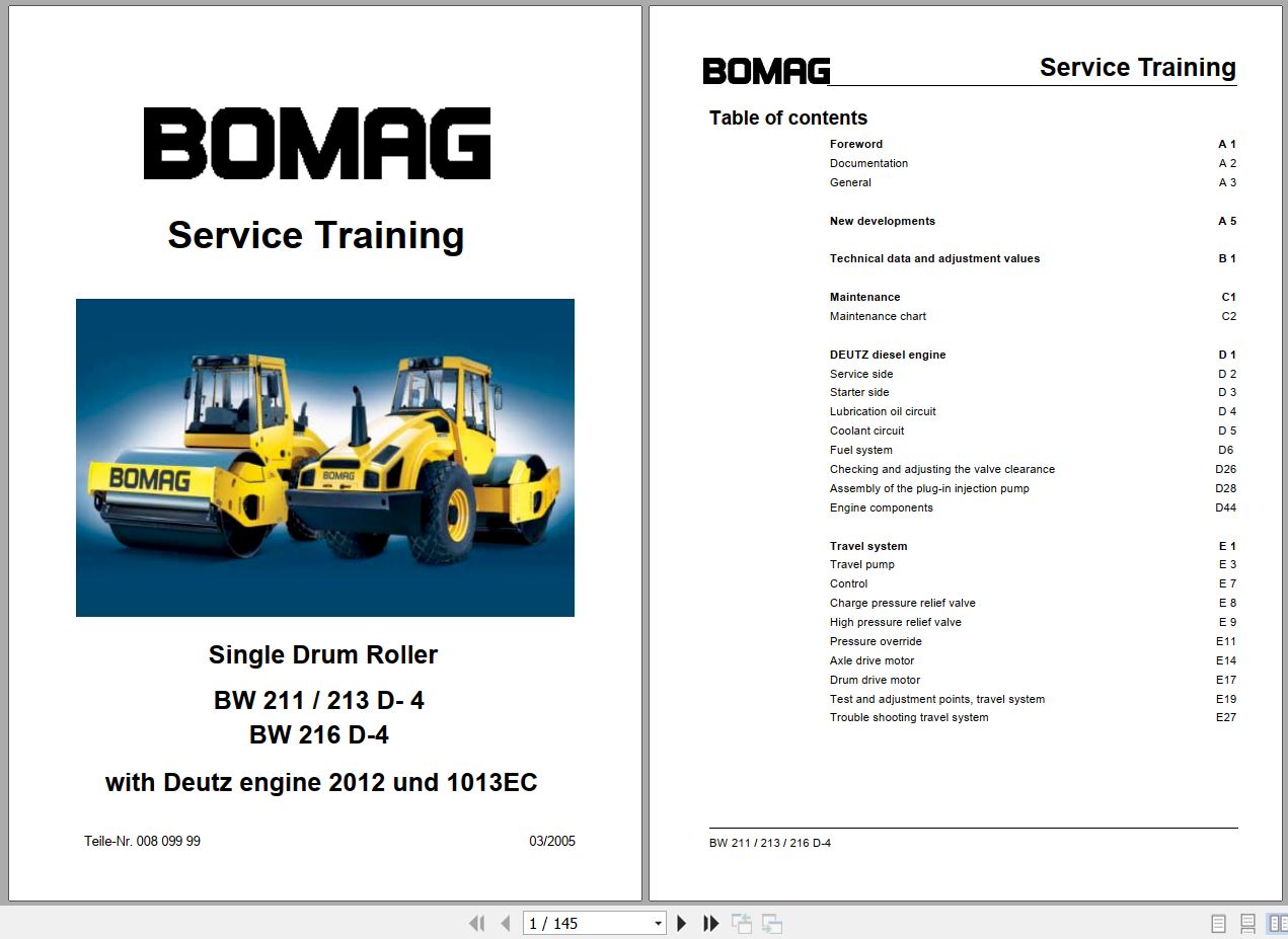
REALEASE :
REALEASE :
-
Bomag Combination Roller BW 120 AC-5 Spare Parts Catalog 00825571 2019-2025
Original price was: 100.80Current price is: 80. USDSize: 158.86 MBFormat: PDFLanguage: English, German, FrenchBrand: BomagType of Machine: Combination RollerType of Manual: Parts ManualModel: Bomag BW 120 AC-5 Combination RollerSerial Number: 101880591001 > 101880591213Part Number: 00825571Year: 2019-2025Number of Pages: 1232 Pages-20%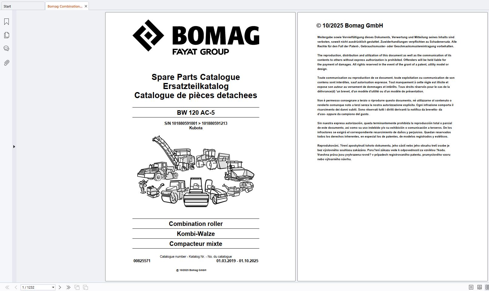
REALEASE :
REALEASE :
-
Bomag Roller BW 211D-4 213D-4 Operating Maintenance Manual
Original price was: 20.15Current price is: 15. USDSize: 5.08 MBFormat: PDFLanguage: EnglishBrand: BomagType of Machine: Single Drum RollerType of Manual: Maintenance Manual, Operating ManualModel: Bomag BW 211D-4, BW 213D-4 Single Drum Roller-25%
REALEASE :
REALEASE :
-
Bomag Machinery Collection Service Manual DVD PDF
Original price was: 400.180Current price is: 180. USDBomag Machinery 8.3GB PDF Service Manual DVDSize: 8.3 GBLanguage: English, DeutschFormat: PDF filesBrand: BOMAGType of document: BOMAG Service ManualAmount of DVD: 1 DVDOS: All Windows 32 & 64 Bit, MACHigh-Speed link DownloadHot-55%
REALEASE :
26.05.2022
REALEASE :
26.05.2022
-
BOMAG Machinery Service Manual Operation Maintenance Manual Combo
Original price was: 800.400Current price is: 400. USDBOMAG Machinery 24.7GB PDF DVD Service Manual, Operation & Maintenance ManualBomag Machinery 2.88GB Updated 03.2021 Electrical Wiring Diagram & Hydraulic Schematic DVDYou will receive full after downloading and extractingOS: All Windows 32 & 64 BitHigh-Speed Link DownloadHot-50%
REALEASE :
29.09.2022
REALEASE :
29.09.2022
-
Bomag Machinery 03.2021 Electrical Wiring Diagram Hydraulic Schematic PDF
Original price was: 600.260Current price is: 260. USDThis is a package for Electrical schematic, Wiring Diagram, and Hydraulic Schematic. You can use this to fix the problem on your vehicle.Hot-57%
REALEASE :
12.08.2022
REALEASE :
12.08.2022
-
Bomag Roller BW141 151 154 AC AD-4 Service Operation Maintenance Manual
20 USDSize: 12.01 MBFormat: PDFLanguage: English, GermanBrand: BomagType of Machine: Tandem RollerType of Manual: Service Training Manual, Operating Manual, Hydraulic Schematic, Electrical DiagramsModel: Bomag Tandem RollerBW 141-151 AD-4, BW 141-151 AC-4, BW 154 AD-4, BW 154 AC-4
REALEASE :
REALEASE :
-
Bomag Roller BW 177 179D-4 And DH-4 Service Training Manual 2004
20 USDSize: 12.79 MBFormat: PDFLanguage: English, GermanBrand: BomagType of Machine: Single Drum RollerType of Manual: Service Training Manual, Hydraulic Schematic, Electrical SchematicModel: Bomag Single Drum RollerBW 177D-4, BW 179D-4, BW 177DH-4, BW 179DH-4
REALEASE :
REALEASE :