
3 ITEMSVIEW CART


Total: 63.00
Expert Support
Full Speed
100% Working
30 USD
Contents:
Section 00 – Safety Precautions
Section 01 – Maintenance
Section 02 – Technical Specifications
1 Loader Backhoe Models
2 Identification Of Main Components
3 Specifications
31 Diesel Engine
32 Transmission
33 Axles
34 Brakes
35 Steering
36 Hydraulic System
37 Front Counterweight
38 Noise And Vibration Levels
39 Buckets
310 Tyres
4 Dimensions And Performance
41 Loader Attachment Dimensions And Performance
42 Dimensions And Performance Of Loader Attachment With Forks
43 Backhoe Attachment Dimensions And Performance
5 Backhoe Attachment Lifting Capacity
6 Maximum Lifting Loads
61 Loader Attachment Maximum Lifting Load Table
62 Backhoe Attachment Maximum Lifting Load Table
7 Supply Summary Table
Section 17 – Torque Converters
1 Powershuttle Torque Converter
11 Description And Operation
12 Specifications
13 Overhaul
14 Inspection
15 Disassembly And Assembly
16 Stall Test
17 Fault Finding
2 Powershift Torque Converter
21 Description And Operation
22 Specifications
23 Overhaul
24 Inspection
25 Disassembly And Assembly
26 Stall Test
27 Fault Finding
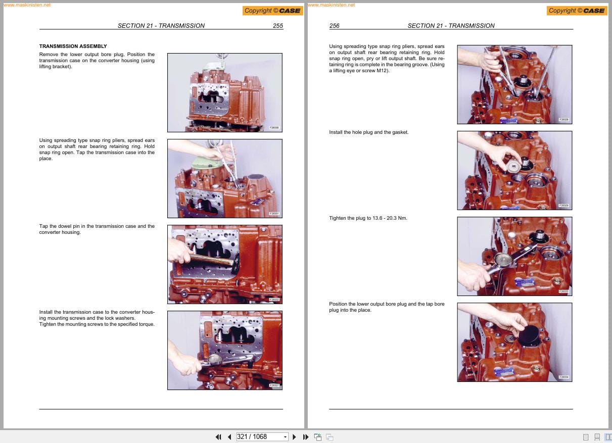
Section 21 – Transmission
1 Powershuttle Transmission “Turner Model Com-T4-2025â€
11 Specifications
12 Mounting Screw Torque
13 Transmission Controls
14 Lubrication
15 Transmission Oil Flow And Supply
16 Transmission Hydraulic Valves And Pressure Test Points
17 Transmission Power Flow
18 Transmission 2wd Components
19 Transmission 4wd Components
110 Transmission Removal
111 Disassembly And Assembly
112 Fault Finding
113 Special Tools
2 Powershift Transmission “Dana T16000â€
21 Specifications
22 Controls
23 Lubrication
24 Pressure Specifications And Check Points
25 Transmission Cooler
26 Hydraulic Diagram
27 Operation
28 Power Flows
29 Gear And Clutch Lay Out
210 Transmission Removal And Installation
211 Transmission Components
212 Disassembly And Assembly
213 Special Tools
214 Fault Finding
215 Fault Finding
Section 25 – Front Axles
1 Front Axle 2wd “Carraroâ€
11 Specifications
12 Disassembly And Assembly
13 Fault Finding
2 Front Axle 4wd “Carraroâ€
21 Specifications
22 Disassembly And Assembly
23 Fault Finding
3 Front Axle 4ws “Carraroâ€
31 Specifications
32 Disassembly And Assembly
33 Fault Finding
4 Special Tools
Section 27 – Rear Axle
1 Rear Axle 2ws
11 Description And Operation
12 Specifications
13 Disassembly And Assembly
14 Fault Finding
2 Rear Axle 4ws “Carraroâ€
21 Specifications
22 Disassembly And Assembly
23 Fault Finding
3 Special Tools
Section 33 – Brakes System
1 Specifications
2 Parking Brake
21 Parking Brake Adjustment
3 Brake Cylinders
4 Oil Brake Tank
5 Bleeding Procedure
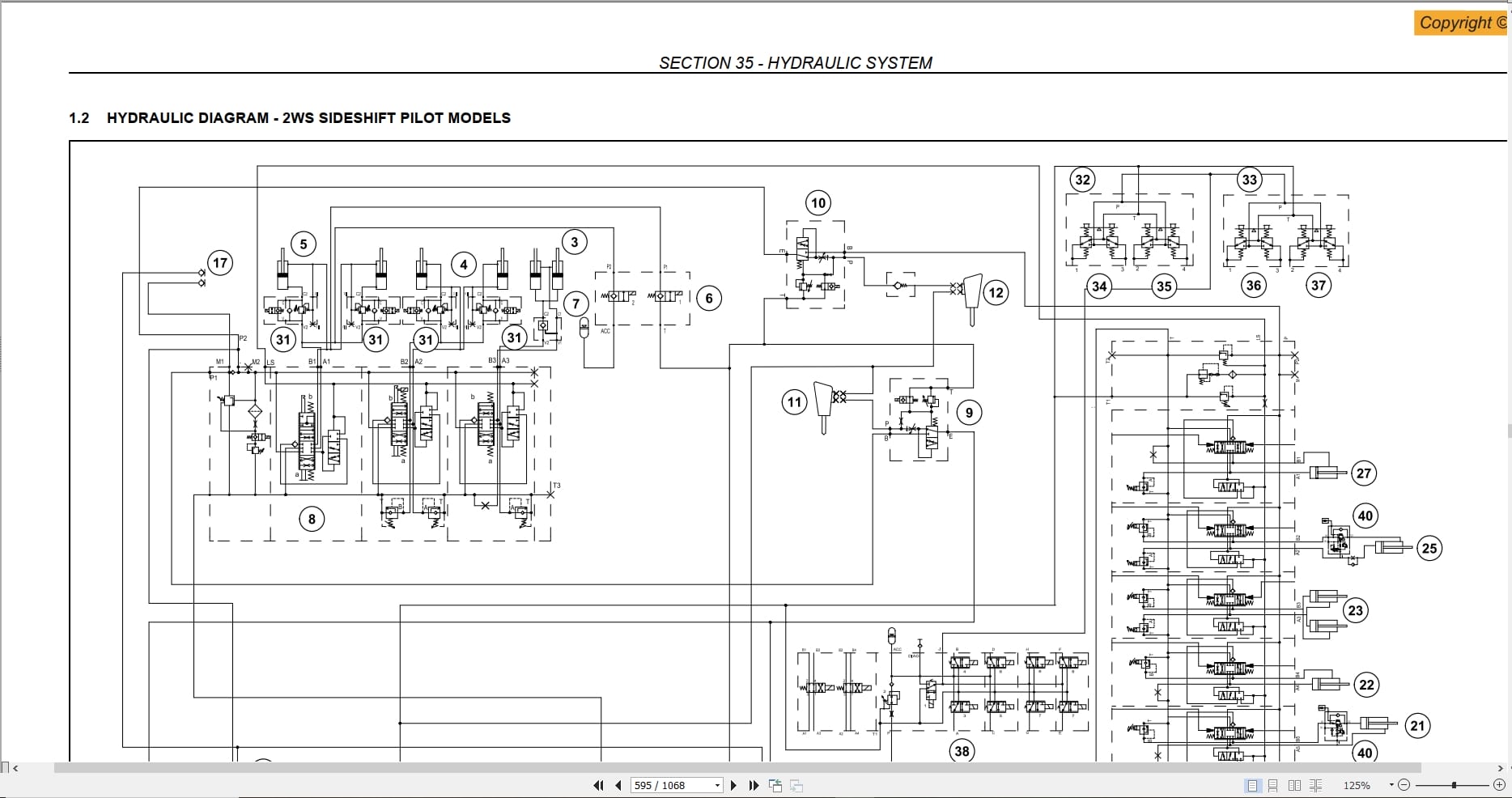
Section 35 – Hydraulic System
1 Hydraulic Diagrams
11 Hydraulic Diagram – 2ws Sideshift Mechanical Models
12 Hydraulic Diagram – 2ws Sideshift Pilot Models
13 Hydraulic Diagram – 4ws Sideshift Mechanical Models
14 Hydraulic Diagram – 4ws Sideshift Pilot Models
15 Hydraulic Diagram – 4ws Center Pivot Pilot Models
2 Hydraulic Pump
21 Description And Operation
22 Specifications
23 Load Sensing Valve
24 Removal
25 Components
26 Disassembly And Assembly
3 Control Valves
31 Control Valves “Rexroth†(Mechanical Models)
32 “Rexroth†Control Valves (Pilot Models)
33 Solenoid Valve For Piloting The Backhoe Control Valve
(With Hydraulic Control)
34 Relief Valves
35 Accumulator “Glide Ride†Parker
4 Hydraulic Swing System
41 Description And Operation
42 Hydraulic Oil Flow
5 Hydraulic Cylinders
51 Loader Attachment Boom Cylinder
52 Loader Bucket Cylinder
53 4×1 Loader Bucket Cylinder
54 Backhoe Boom Cylinder
55 Backhoe Attachment Dipper Cylinder
56 Backhoe Bucket Cylinder
57 Telescopic Cylinder
58 4ws Stabilizer Cylinder – Center Pivot
59 Stabilizer Cylinder – Sideshift
510 Swing Cylinder
511 Backhoe Attachment Sideshift Cylinder – Sideshift
512 Special Tools
6 Hydraulic Control Levers
61 Specifications
62 Description And Operation
63 Disassembly And Assembly
64 Control Lever Valve
7 Fault Finding
71 Preliminary Checks
72 Fault Finding
Section 39 – Chassis
1 Description And Operation
2 Removal And Installation Components
21 Components Within The Chassis
22 Components Below The Chassis
23 Components Attached Outside The Chassis
24 Components Attached On The Chassis
25 Mounting Screw Torque
Section 41 – Steering System
1 Steering System 2ws
2 Steering System 4ws
3 Power Steering
31 Specifications
32 Components
33 Disassembly And Assembly
34 Special Tools
35 Fault Finding
Section 50 – Cab Heating And Air Conditioning
1 Specifications
2 Cab Heating
21 Description And Operation
3 Air Conditioning
31 Principals Of Air Conditioning
32 Safety Precautions
33 Controls And Operation
34 Fault Finding And Testing
35 Flushing The System
36 Evacuating The System
37 Charging The System
38 Components Overhaul
39 Compressor
310 Special Tools
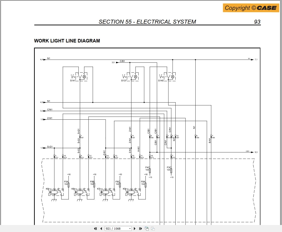
Section 55 – Electrical System
1 Generalities
11 Temporary Wiring Harness Repair
12 Fault Finding
2 Electrical Diagrams
21 Electrical Diagrams – Powershuttle Rops (580sr)
22 Electrical Diagrams – Powershuttle Cab (580sr)
23 Electrical Diagrams – Powershift Cab (580sr)
24 Electrical Diagrams – Powershuttle Cab (580sr+/590sr)
25 Electrical Diagrams – Powershift Cab (590sr)
26 Electrical Diagrams – 4ws Powershift Cab (695sr)
3 Controls And Instruments
31 Front Control Panels (580sr / 590sr)
32 Front Control Panels (695sr)
33 Side Instrument Cluster Panel (580sr)
34 Side Instrument Cluster Panel (580sr+ / 590sr / 695sr)
35 Side Instrument Cluster (580sr)
36 Side Instrument Cluster (580sr+ / 590sr / 695sr)
37 Immobiliser Circuit
4 Diagnostic Display (580sr+ / 590sr / 695sr)
41 Symbols
42 Setup Menu
43 Procedure About Self Test
44 On Board Error Code Retrieval
45 Backlighting And Dimming
46 Work Hours
47 Functional Description
48 Warning System
49 Maintenance
410 Warning Messages
5 Starting System
51 Description And Operation
52 Fault Finding
53 Starter Motor
6 Alternator
61 Specifications
62 Description And Operation
63 Components
64 Removal
65 Preliminary Check And Tests
66 Fault Finding
7 Battery
71 Specifications
72 Description And Operation
73 Battery Replacement
74 Maintenance
75 Tests
76 Connecting A Booster Battery
77 Battery Master Switch
8 Component Testing
81 General Introduction
82 Component Testing
83 Ground Points
84 Alternator
85 Transmissions
86 Parking Brake Switch
87 Cab
88 4wd Switch
89 Brake Pedal Switches
810 Brake Oil Level Warning Lamp
811 Front Work Lamp Switch (1) – Rear Work Lamp Switch (2) Main Light Switch
812 Hazard Switch
813 Hazard Warning Light Relay
814 Multi Function Switch
815 Front Windshield Wiper Motor (1) – Rear Windshield Wiper Motor (2)
816 4ws – Steering Selector Switch
817 Steering Control Unit
818 4ws Rear Axle Steering Sensor
819 4ws Front Axle Steering Sensor
820 Steering Solenoid Valve
821 Differential Lock Switch (1)
822 Loader
823 Backhoe
Section 82 – Loader
1 Loader Attachment Controls
11 Loader Attachment Operation
2 Loader Bucket Self Leveling
3 Loader Attachment Safety Strut
4 Loader Bucket Removal
5 Loader Removal
Section 84 – Backhoe
1 Description And Operation
2 Backhoe Attachment Mechanical Controls Version
3 Backhoe Attachment Hydraulic Controls
4 Removal And Installation
41 Center Pivot Backhoe Attachment Disassembly
42 Backhoe Attachment Disassembly – Sideshift
43 Backhoe Bucket Removal
44 Bucket Teeth Replacement
45 Dipper Remove
5 Telescopic Dipper Revision
6 Telescopic Dipper Revision
7 Revisione Del Braccio Telescopico

REALEASE :
22.07.2020
REALEASE :
22.07.2020
REALEASE :
13.04.2022
REALEASE :
28.05.2019
REALEASE :
28.05.2019

REALEASE :
28.05.2019
REALEASE :
28.05.2019

REALEASE :
02.07.2022
REALEASE :
02.07.2022

REALEASE :
28.05.2019
REALEASE :
28.05.2019

REALEASE :
17.04.2020
REALEASE :
17.04.2020
REALEASE :
09.06.2019
REALEASE :
09.06.2019
 Automotive - Heavy Equipment - Truck & Bus - Forklift - Crane