
0 ITEMSVIEW CART

✓
Expert Support
✓
Full Speed
✓
100% Working
CAT Telehandler TH414 TH514 TH417 Parts Manual 31200488
Size: 36.90 MB
Format: PDF
Language: English
Brand: Caterpillar
Type of Machine: Telehandler
Type of Manual: Parts Manual
Model: CAT TH414 TH514 TH417 Telehandler
Serial Number:
S/N TBZ00100 & After
S/N TBW00100 & After
S/N TBT00100 & After
Part Number: 31200488
Publication Date: 2010
Number of Pages: 398 Pages
10 USD
- Description
Description
Contents:
Section 1 Frame & Attaching Parts
Figure 1-1 Frame Shrouding & Trim
Figure 1-2 Frame Shrouding & Trim – Engine Pod Installation
Figure 1-3 Axle & Wheel Mounting
Figure 1-4 Outrigger Installation
Figure 1-5 Hitches
Section 2 Boom
Figure 2-1 Boom Assembly Components
Figure 2-2 Boom Chain Assembly
Figure 2-3 First Boom Section Assembly
Figure 2-4 Second Boom Section Assembly
Figure 2-5 Third Boom Section Assembly
Figure 2-6 Fourth Boom Section Assembly
Figure 2-7 Quick Coupler & Quick Disconnect Installation
Figure 2-8 Boom Prop Installation
Section 3 Attachments
Figure 3-1 Carriage Assembly
Figure 3-2 Forks
Figure 3-3 Side Shift Carriage
Figure 3-4 Rotate/Side Tilt Carriage
Figure 3-5 General Purpose Bucket
Figure 3-6 Multi-Purpose Bucket
Figure 3-7 Material Handling Bucket
Figure 3-8 Grapple Bucket
Figure 3-9 Truss Boom
Figure 3-10 Lifting Hook
Figure 3-11 Platform Installations
Figure 3-12 THP18s Platform Installation
Figure 3-13 THP45s Platform Installation
Figure 3-14 Console Box Assembly
Section 4 Engine & Attaching Parts
Figure 4-1 Engine & Transmission Installation
Figure 4-2 CAT Engine
Figure 4-3 Fuel Line Installation
Figure 4-4 Fuel Tank Installation
Figure 4-5 Radiator Installation
Figure 4-6 Air Cleaner Installation
Figure 4-7 Muffler Installation
Figure 4-8 Block Heater Installation
Section 5 Drive Train
Figure 5-1 Front Axle Assembly
Figure 5-2 Front Axle – Axle Housing
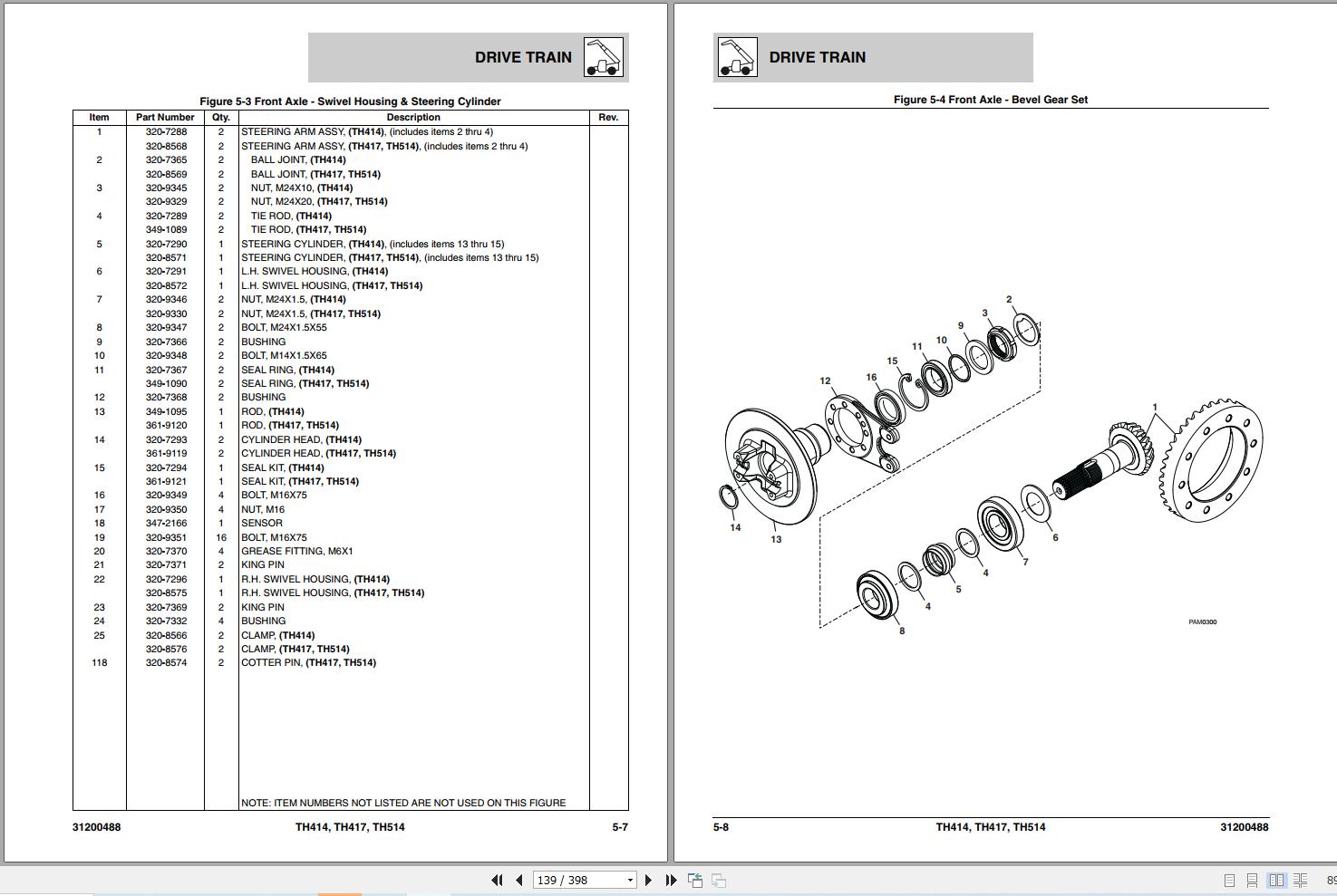
Figure 5-3 Front Axle – Swivel Housing & Steering Cylinder
Figure 5-4 Front Axle – Bevel Gear Set
Figure 5-5 Front Axle – Differential
Figure 5-6 Front Axle – Double U-Joint
Figure 5-7 Front Axle – Brakes
Figure 5-8 Front Axle – Wheel Hub
Figure 5-9 Front Axle – Final Reduction
Figure 5-10 Front Axle – Brake Caliper
Figure 5-11 Rear Axle Assembly
Figure 5-12 Rear Axle – Axle Housing
Figure 5-13 Rear Axle – Swivel Housing & Steering Cylinder
Figure 5-14 Rear Axle – Bevel Gear Set
Figure 5-15 Rear Axle – Differential
Figure 5-16 Rear Axle – Double U-Joint
Figure 5-17 Rear Axle – Wheel Hub
Figure 5-18 Rear Axle – Final Reduction
Figure 5-19 Drive Shaft Installation
Figure 5-20 Remote Grease System Installation
Figure 5-21 Tire & Wheel Installation
Section 6 Cab
Figure 6-1 Cab Installation
Figure 6-2 Cab Assembly
Figure 6-3 Interior Installation
Figure 6-4 Cab Door & Window Installation
Figure 6-5 Wiper System
Figure 6-6 Cab Covers & Cab Guards
Figure 6-7 Cloth Mechanical Suspension Seats
Figure 6-8 Cloth Pneumatic Suspension Seats
Figure 6-9 Cab Heater/AC Components
Figure 6-10 Engine Heater/AC Components
Figure 6-11 Heater/AC Unit & Heater/AC Unit Guard Shield
Section 7 Controls
Figure 7-1 Joystick
Figure 7-2 Steering Column
Figure 7-3 Accelerator Pedal
Figure 7-4 Mechanical Handbrake
Figure 7-5 Brake Installation
Section 8 Hydraulic Circuits
Figure 8-1 Supply Circuit
Figure 8-2 Dump Circuit
Figure 8-3 Steer Select
Figure 8-4 Service Brake
Figure 8-5 Lift Cylinder
Figure 8-6 Extend/Retract
Figure 8-7 Tilt & Tilt Compensation
Figure 8-8 Auxiliary Hydraulics
Figure 8-9 Frame Level & Outrigger
Figure 8-10 Platform Hydraulics
Section 9 Hydraulic Components
Figure 9-1 Lift Cylinder
Figure 9-2 Extend/Retract Cylinder
Figure 9-3 Tilt Cylinder
Figure 9-4 Compensation Cylinder
Figure 9-5 Frame Level Cylinder
Figure 9-6 Outrigger Cylinder
Figure 9-7 Quick Coupler Cylinder
Figure 9-8 Platform Rotate Cylinder
Figure 9-9 Main Control Valve
Figure 9-10 Piston Pump
Figure 9-11 Steering Select Valve
Figure 9-12 Hydraulic Tank Installation
Figure 9-13 Diverter Valve
Figure 9-14 Outrigger & Frame Level Valve
Figure 9-15 Double Pilot Check Valve
Section 10 Electrical
Figure 10-1 Engine & Transmission Electronic Installation
Figure 10-2 Cab Electronic Installation
Figure 10-3 Cab Switches
Figure 10-4 Boom & Frame Electrical Installation
Figure 10-5 Worklight & License Plate Light Installations
Figure 10-6 Driving Light Installation
Figure 10-7 Frame Electronic Installation – If Equipped For Platform
Figure 10-8 Engine Harness
Figure 10-9 Cab Floor Harness
Figure 10-10 Cab Roof Harness
Figure 10-11 Transmission Harness
Figure 10-12 Front Frame Harness
Figure 10-13 Rear Frame Harness
Figure 10-14 Boom Worklight Harness
Figure 10-15 Auxiliary Hydraulic Harness
Figure 10-16 LMIS Installation
Figure 10-17 LMIS Beacon Installation
Figure 10-18 LMIS Harness
Section 11 Decals
Figure 11-1 Cab & Frame Decals
Figure 11-2 Boom Decals
Figure 11-3 Platform Decals
Maintenance parts list
Part Number Index
Related Products
-
Caterpillar Forklift Operation Maintenance Service Manuals Collection
Original price was: 200.100Current price is: 100. USDThis is a service information package, you will need to use this to repair a vehicleHot-50%
REALEASE :
REALEASE :
-
Caterpillar Truck 83.5 MB PDF Collection Wiring Diagram
Original price was: 100.80Current price is: 80. USDLanguage: EnglishSize: 83.5 MBFormat: PDFBrand: CaterpillarType of Manual: Wiring DiagramType of Machine: TruckHot-20%
REALEASE :
REALEASE :
-
CAT Forklift MCFE Spare Parts Catalog PDF Request
Price range: 45 through 200 USDThis is an offline spare parts catalog, you need to use this to sell the spare parts and it can help you a little with assembly. It’s from a manufacturer and the best in the world.Hot
REALEASE :
REALEASE :
-
Linde Diagnostic Program Truck Doctor v2.01.05 01.2016
Original price was: 40.30Current price is: 30. USDThis is a diagnostic program. You will need this when you are a technician.Hot-25%
REALEASE :
REALEASE :
-
CAT Dragline Collection Service Library PDF DVD
Original price was: 300.180Current price is: 180. USDThis is a service information package, you will need to use this to repair a vehicleHot-40%
REALEASE :
21.10.2022
REALEASE :
21.10.2022
-
CAT Beamed Stageloader Collection Service Library PDF DVD
Original price was: 100.80Current price is: 80. USDThis is a service information package, you will need to use this to repair a vehicleHot-20%
REALEASE :
21.10.2022
REALEASE :
21.10.2022
-
CAT Armored Face Conveyor Collection Service Library PDF DVD
Original price was: 300.140Current price is: 140. USDThis is a service information package, you will need to use this to repair a vehicleHot-53%
REALEASE :
21.10.2022
REALEASE :
21.10.2022
-
Caterpillar Service Parts Manual CE PDF Collection 158 GB
800 USDThis is a service information package, you will need to use this to repair a vehicleHot
REALEASE :
REALEASE :