
0 ITEMSVIEW CART


✓
Expert Support
✓
Full Speed
✓
100% Working
Caterpillar Engine C1.1 (MBH00001 -) Service Manual
Size: 39.2 MB
Format: PDF
Language: English
Brand: Caterpillar
Type of Machine: Engine
Type of Manual: Electric Diagram, Service Manual
Model: Caterpillar C1.1 Engine
Serial Number: (MBH00001 -)
Number of Pages: 870 Pages
30 USD
- Description
Description
Contents:
Fuel Filter Base – Remove and Install – C1.1 and C1.7 Engines
Removal Procedure
Installation Procedure
Fuel Filter Base – Remove – C1.1 – If Equipped
Removal Procedure
Fuel Filter Base – Install – C1.1 – If Equipped
Installation Procedure
Fuel Transfer Pump – Remove and Install – Mechanical Transfer Pump – Type 2
Removal Procedure
Installation Procedure
Fuel Injection Lines – Remove and Install
Removal Procedure
Installation Procedure
Fuel Shutoff Solenoid – Remove and Install
Removal Procedure
Installation Procedure
Fuel Injection Pump – Remove and Install
Removal Procedure
Installation Procedure
Fuel Injector – Remove and Install
Removal Procedure
Installation Procedure
Turbocharger – Remove and Install – C1.1 Turbocharged Engines
Removal procedure
Installation procedure
Exhaust Manifold – Remove and Install – C1.1 Engines – If Equipped
Removal Procedure
Installation Procedure
Inlet and Exhaust Valve Springs – Remove and Install
Removal Procedure
Installation Procedure
Inlet and Exhaust Valves – Remove and Install
Removal Procedure
Installation Procedure
Engine Oil Line – Remove and Install – C1.1 Engines
Removal Procedure
Installation Procedure
Engine Oil Line – Remove and Install – C1.1 and C1.7 Engines
Removal Procedure
Installation Procedure
Engine Oil Cooler – Remove and Install – Turbocharged Engines Only
Removal Procedure
Installation Procedure
Engine Oil Cooler – Remove and Install – C1.1 Turbocharged Engines Only
Removal Procedure
Installation Procedure
Engine Oil Relief Valve – Remove and Install
Removal Procedure
Installation Procedure
Engine Oil Pump – Remove – C0.5 and C0.7 Engines
Removal Procedure
Method Two for Idler Hub Removal
Engine Oil Pump – Install
Installation Procedure
Method Two for Installation of Idler Hub
Water Pump – Remove and Install – C1.1 and C1.7 Engines
Removal Procedure For Type One Water Pump
Installation Procedure For Type One Water Pump
Removal Procedure For Type Two Water Pump
Installation Procedure For Type Two Water Pump
Water Pump – Remove and Install – C0.5 and C0.7 Engines
Removal Procedure
Installation Procedure
Water Pump – Remove and Install – C1.1 Engines
Removal Procedure
Installation Procedure
Water Temperature Regulator Housing – Remove and Install
Removal Procedure
Installation Procedure
Water Temperature Regulator – Remove and Install – C1.1 and C1.7 Engines.
Removal Procedure
Installation Procedure
Flywheel – Remove – C1.1 Engines – Type 1
Removal Procedure
Flywheel – Remove – C1.1 And C1.7 Engines – Type 2
Removal Procedure
Flywheel – Remove – C1.1 Engines – Type 3
Removal Procedure
Flywheel – Install – C1.1 Engines – Type 1
Installation Procedure
Flywheel – Install – C1.1 And C1.7 Engines – Type 2
Installation Procedure
Flywheel – Install – C1.1 Engines – Type 3
Installation Procedure
Crankshaft Rear Seal – Remove and Install
Removal Procedure
Installation Procedure
Crankshaft Wear Sleeve (Rear) – Remove and Install
Removal Procedure
Installation Procedure
Flywheel Housing – Remove and Install
Removal Procedure
Installation Procedure
Flywheel Housing – Remove and Install – Engines with Flywheel Housing and Back Plate
Removal Procedure
Installation Procedure
Crankshaft Pulley – Remove and Install
Removal Procedure
Installation Procedure
Crankshaft Front Seal – Remove and Install
Removal Procedure
Alternative Removal Procedure
Installation Procedure
Housing (Front) – Remove
Removal Procedure
Housing (Front) – Disassemble
Disassembly Procedure
Housing (Front) – Assemble
Assembly Procedure
Housing (Front) – Install
Installation Procedure
Crankcase Breather – Remove and Install – Turbocharged Engines – Type 1
Removal Procedure
Installation Procedure
Crankcase Breather – Remove and Install – Turbocharged Engines – Type 2
Removal Procedure
Breather Heater Remove
Installation Procedure
Breather Heater Install
Valve Mechanism Cover – Remove and Install – C1.1 Engines
Removal Procedure
Installation Procedure
Rocker Shaft and Pushrod – Remove
Removal Procedure
Rocker Shaft – Disassemble – C0.5, C0.7, C1.1, and C1.7 Engines
Disassembly Procedure
Rocker Shaft – Assemble – C0.5, C0.7, C1.1, and C1.7 Engines
Assembly Procedure
Rocker Shaft and Pushrod – Install
Installation Procedure
Cylinder Head – Remove
Removal Procedure
Cylinder Head – Install
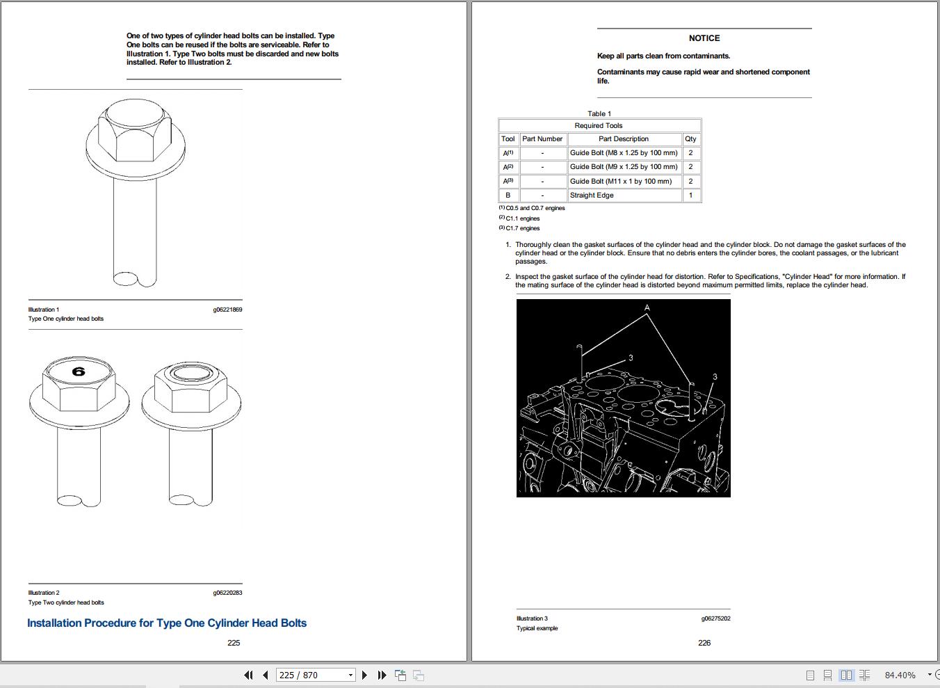
Installation Procedure for Type One Cylinder Head Bolts
Installation Procedure for Type Two Cylinder Head Bolts
Lifter Group – Remove and Install
Removal Procedure
Installation Procedure
Camshaft – Remove
Removal Procedure
Camshaft – Disassemble
Disassembly Procedure
Camshaft – Assemble
Assembly Procedure
Camshaft – Install
Installation Procedure
Camshaft Bearings – Remove and Install
Removal Procedure
Installation Procedure
Engine Oil Pan – Remove and Install – C1.1 and C1.7 Engines
Removal Procedure
Installation Procedure
Pistons and Connecting Rods – Remove
Removal Procedure
Pistons and Connecting Rods – Disassemble
Disassembly Procedure
Pistons and Connecting Rods – Assemble
Assembly Procedure
Pistons and Connecting Rods – Install
Installation Procedure
Connecting Rod Bearings – Remove – Connecting rods in position
Removal Procedure
Connecting Rod Bearings – Install – Connecting rods in position
Installation Procedure
Crankshaft Main Bearings – Remove
Removal Procedure
Crankshaft Main Bearings
Crankshaft Bearing (Front)
Crankshaft Main Bearings – Install
Installation Procedure
Crankshaft Main Bearings
Crankshaft Bearing (Front)
Crankshaft – Remove – C1.1 Engines
Removal Procedure
Crankshaft – Remove
Removal Procedure
Crankshaft – Install – C1.1 Engines
Installation Procedure
Crankshaft – Install
Installation Procedure
Bearing Clearance – Check
Measurement Procedure
Coolant Temperature Switch – Remove and Install – C1.1 and C1.7 Engines
Removal Procedure
Installation Procedure
Engine Oil Pressure Switch – Remove and Install – Type 2
Removal Procedure
Installation Procedure
Glow Plugs – Remove and Install
Removal Procedure
Installation Procedure
V-Belts – Remove and Install
Removal Procedure
Installation Procedure
Fan – Remove and Install
Removal Procedure
Installation Procedure
Alternator – Remove and Install – 65 AMP Alternator C1.1 Engines
Removal Procedure
Installation Procedure
Alternator – Remove and Install – 15 AMP Alternator C1.1 Engines
Removal Procedure
Installation Procedure
Alternator – Remove and Install – 15 AMP Alternator C1.1 Engines
Removal Procedure
Installation Procedure
Alternator – Remove and Install – 40 AMP Alternator C1.1 Engines
Removal Procedure
Installation Procedure
Electric Starting Motor – Remove and Install – Type 2
Removal Procedure
Installation Procedure
Electric Starting Motor – Remove and Install – Type 3
Removal Procedure
Installation Procedure
Duo-Cone Seals – Install
DUO CONE SEALS
Background
GENERAL INFORMATION
Recommended Cleaning Wipes
Service Kits
STORAGE
Seal and Seal Ring Storage
CLEANLINESS
Seals, Seal Rings, and Housing Cleanliness
Housing Retainer Lip Cleanliness
HANDLING
Toric Handling
Seal Ring Handling
Housing Handling
PREASSEMBLY INSPECTION OF CRITICAL COMPONENTS
Seal Inspection – Rubber Toric
Seal Ring
Guidelines to be followed
Miscellaneous Defects
Seal Ring Ramp
Housing (Seal Retainer)
Housing Ramp
DUO-CONE SEAL ASSEMBLY TOOLING
Duo-Cone Seal Ring Installation Tool
Rubber Mallets and Soft Hammers
Tooling Inspection
Tooling Damage
Tooling – Care, Maintenance, and Damage Reporting
Tooling Use
Measurement
Tooling Storage Cleanliness
Duo-Cone Seal Assembly Tooling Storage
ASSEMBLY AIDS
Assembly Lubricants/Cleaners for Use on Rubber Toric
Assembly Lubricants for Pre lube of Use on Seal Ring Face
Assembly Cleaner Application
Assembly Lubricant Application
Assembly Cleaners for Use on Housing Retainer
ASSEMBLY INSTRUCTIONS AND PROCEDURES
PRE-ASSEMBLY
General Assembly
General Assembly Requirements
Assembly of Small Duo-Cone Seals
Assembly of Medium and Large Duo-Cone Seals
Removing & Reinstalling a Rubber Toric to a Metal Seal Ring
Alternate Method of Assembling of Duo-Cone Seal with Silicone Rubber Toric
Verifying Duo-Cone Seal Assembly
Results of Incorrect Assembly
Final Assembly of Duo-Cone Seal Group
Results of Incorrect Assembly of the Duo-Cone Seal Group
FAILURE MODES DISCUSSION
Lip Type Seals – Install
LIP TYPE SEALS
Background
STORAGE
Sealing Journal Storage
Bore Storage
CLEANLINESS
Seal Cleanliness
Bore & Sealing Journal/Contact Surface Cleanliness
Tooling Cleanliness
Tooling Storage Cleanliness
HANDLING
Handling of the Seal
Handling of Mating Components
Assembly Aids
Assembly Tooling
Types of Lip Seal Tooling
Tooling – Care
Tooling – Inspection
Tooling – Storage
Tooling – Maintenance & Damage Reporting
Preassembly Inspection Of Critical Components
Lip Type Seals – Assembly
Seal Lubrication Application
Lubrication Location
Sealant Use
Assembly Tooling Use
Lip Seal Installation Protection
O-Ring Seals – Install – RADIAL, FITTING ASSEMBLY O-RINGS & OTHER O-RING APPLICATIONS
O-RINGS INSTALLED IN STOR/ORFS FITTINGS (FITTING/ADAPTOR ASSEMBLIES)
Background
Assembly Tooling
Types of Installation Tooling
STOR Installation Tool
Tool Ordering Information
ORFS Insertion Tool
Tool Ordering Information
Tooling – Possible Damage
Assembly Tooling – Storage
Tooling – Care
Recommended Cleaning Wipes:
TOOLING – INSPECTION
TOOLING – CRITICAL MAINTENANCE & DAMAGE REPORTING PROCESS
ASSEMBLY
ORFS Assembly
ORFS Assembly Procedure
STOR Assembly
STOR Assembly Procedures
Assembly Storage
O-RINGS INSTALLED IN FACE SEAL JOINTS (NON-ADAPTOR APPLICATIONS)
Background
Handling
Assembly Aid – Retention Compounds
Retention Compound Application
Recommended Cleaning Wipes:
Assembly
O-RINGS INSTALLED IN RADIAL SEAL JOINTS
Background
Handling
Assembly Aids – Seal Lubricants
Assembly Aid – Approved Seal Lubricants
PTFE Coating
P-80
Fluid Being Sealed
Low Pressure AC Line Lubricants
Lubricant Dispensers
Lubricant Application
Tooling – Inspection
ASSEMBLY TOOLING:
Assembly
Foreword
California Proposition 65 Warning
Literature Information
Safety
Operation
Maintenance
Maintenance Intervals
Overhaul
Safety Messages
General Hazard Information
Pressurized Air and Water
Fluid Penetration
Containing Fluid Spillage
Static Electricity Hazard when Fueling with Ultra-low Sulfur Diesel Fuel
Lines, Tubes, and Hoses
Inhalation
Exhaust
Hexavalent Chromium
Asbestos Information
Softwrap
Dispose of Waste Properly
Burn Prevention
Coolant
Oils
Batteries
Fire Prevention and Explosion Prevention
Fire Extinguisher
Ether
Lines, Tubes, and Hoses
Crushing Prevention and Cutting Prevention
Mounting and Dismounting
Before Starting Engine
Engine Starting
Engine Stopping
Electrical System
Grounding Practices
Model View Illustrations
C0.5 Engine
C0.7 Engine
C1.1 Turbocharged Engine
C1.7 Engine
C1.7 Turbocharged Engine
Fuel System Components
Components for Electronic Control
Engine Description
Engine Specifications
C0.5 Engine
C0.7 Engine
C1.1 Engine
C1.1 Turbocharged Engine
C1.7 Engine
C1.7 Turbocharged Engine
Plate Locations and Film Locations
Serial Number Plate (1)
Reference Numbers
Record for Reference
Emissions Certification Film
Product Lifting
Product Storage
Gauges and Indicators
Sensors and Electrical Components
Engine Shutoffs and Engine Alarms
Shutoffs
Alarms
Testing the Shutoff and Alarm System
Fuel Shutoff
Overspeed
Before Starting Engine
Starting the Engine
Cold Weather Starting
Starting with Jump Start Cables
After Starting Engine
Engine Operation
General Engine Operation
Carbon Dioxide (CO2) Emissions Statement
Engine Warm-up
Engaging the Driven Equipment
Fuel Conservation Practices
Stopping the Engine
Emergency Stopping
Emergency Stop Button
After Stopping Engine
Radiator Restrictions
Fuel and the Effect from Cold Weather
Fuel Related Components in Cold Weather
Fuel Tanks
Fuel Filters
Fuel Heaters
Refill Capacities
Lubrication System
C0.5 Engine
C0.7 Engine
C1.1 Engine
C1.7 Engine
Cooling System
C0.5 Engine
C0.7 Engine
C1.1 Engine
C1.7 Engine
Fluid Recommendations
Engine Lubrication Oil
Cat DEO-ULS
Commercial Oils
Lubricant Viscosity Recommendations
S·O·S Oil Analysis
Lubricating Grease
Fuel
Fuel Additives
Coolant
S·O·S Coolant Analysis
System Pressure Release
Coolant System
Fuel System
High-Pressure Fuel Lines (If Equipped)
Engine Oil
Welding on Engines with Electronic Controls
Maintenance Interval Schedule
When Required
Daily
Every 50 Service Hours or Weekly
Every 250 Service Hours
Every 250 Service Hours or 6 Months
Every 250 Service Hours or 1 Year
Initial 500 Hours (for New Systems, Refilled Systems, and Converted Systems)
Every 500 Service Hours
Every 500 Service Hours or 1 Year
Every 1000 Service Hours
Every 2000 Service Hours
Every Year
Every 3000 Service Hours
Every 3000 Service Hours or 2 Years
Every 4000 Service Hours
Every 6000 Service Hours or 3 Years
Every 12 000 Service Hours or 6 Years
Overhaul
Commissioning
Aftercooler Core – Clean/Test – Air-To-Air Aftercooler
Aftercooler Core – Inspect
Alternator – Inspect
Alternator and Fan Belts – Inspect/Adjust
Inspection
Adjustment
Alternator and Fan Belts – Replace
Battery – Replace
Battery Electrolyte Level – Check
Battery or Battery Cable – Disconnect
Cooling System Coolant (DEAC) – Change
Drain
Flush
Cooling Systems with Heavy Deposits or Plugging
Fill
Cooling System Coolant (ELC) – Change
Drain
Flush
Fill
Cooling System Coolant Extender (ELC) – Add
Cooling System Coolant Level – Check
Cooling System Coolant Sample (Level 1) – Obtain
Cooling System Coolant Sample (Level 2) – Obtain
Cooling System Supplemental Coolant Additive (SCA) – Test/Add
Test for SCA Concentration
Coolant and SCA
Water and SCA
S·O·S Coolant Analysis
Level 1
Level 2
Add the SCA, If Necessary
Cooling System Water Temperature Regulator – Replace
Driven Equipment – Check
Engine – Clean
Engine Air Cleaner Element – Replace
Servicing the Air Cleaner Element
Engine Air Cleaner Service Indicator – Inspect – If Equipped
Test the Service Indicator
Engine Air Precleaner – Check/Clean
Engine Crankcase Breather – Replace
Engine Mounts – Inspect
Engine Oil Level – Check
Engine Oil Sample – Obtain
Obtain the Sample and the Analysis
Engine Oil and Filter – Change
Oil and Filter Change Intervals
Drain the Engine Oil
Replace the Oil Filter
Fill the Engine Crankcase
Engine Protective Devices – Check
Visual Inspection
Engine Valve Lash – Inspect/Adjust
Fan Clearance – Check
Fuel Injector – Test/Change
Removal and Installation of the Fuel Injection Nozzles
Fuel System – Prime
Mechanical Priming Pump
Primary Filter
Priming the Primary Fuel Filter
Secondary Fuel filters
Priming the system
Hand Priming Pump 6
In-line Priming Pump 7
Electrical Priming Pump 8
Fuel Transfer Pump 9
Fuel System Primary Filter/Water Separator – Drain
Fuel System Secondary Filter – Replace
Fuel Filter with Canister
Fuel Filter with Element
Fuel filter with priming pump
Fuel Tank Water and Sediment – Drain
Fuel Tank
Drain the Water and the Sediment
Fuel Storage Tanks
Hoses and Clamps – Inspect/Replace
Inspect Tubes, Hoses, Bellows, and Clamps
Replace the Hoses and the Clamps
Cooling System
Fuel System
Lubrication System
Air System
Overhaul Considerations
Oil Consumption as an Overhaul Indicator
Overhaul Recommendation
Cleaning
Obtain Coolant Analysis
S·O·S Coolant Analysis (Level II)
Radiator – Clean
Severe Service Application – Check
Environmental Factors
Improper Operating Procedures
Improper Maintenance Procedures
Starting Motor – Inspect
Turbocharger – Inspect – If Equipped
Removal and Installation
Inspecting
Walk-Around Inspection
Inspect the Engine for Leaks and for Loose Connections
Water Pump – Inspect
Emissions Warranty Information
Engine Rating Conditions
Engine Rating Definitions
Customer Assistance
USA and Canada
Outside of the USA and of Canada
Ordering Replacement Parts
Reference Material
Lubricants
Fuels
Coolants
Miscellaneous
Emissions Warranty
Additional Reference Material
Maintenance Records
Maintenance Log
Engine Design
C0.5 Engine
C0.7 Engine
C1.1 Engine
C1.1 Turbocharged Engine
C1.7 Engine
C1.7 Turbocharged Engine
Fuel Injection Lines
Fuel Injection Pump
Fuel Injection Nozzles
Fuel Transfer Pump
Lifter Group
Rocker Shaft
Valve Mechanism Cover
Cylinder Head Valves
Cylinder Head
Tightening Procedure for the Cylinder Head
C0.5 Engine
C0.7 and C1.1 Engines
C1.7 Engine
Type One Cylinder Head Bolts
Type Two Cylinder Head Bolts
Measuring the Distortion of the Cylinder Head
Exhaust Manifold
Camshaft
Engine Oil Lines
Engine Oil Filter
Engine Oil Relief Valve
Engine Oil Pump
Engine Oil Pan
Oil Suction Tube and Oil Strainer
Water Temperature Regulator
Water Temperature Regulator Housing for C0.5 and C0.7 Engines
Water Temperature Regulator Housing for C1.1 and C1.7 Engines
Cylinder Block
Crankshaft
Connecting Rod Bearing Journal
Main Bearing Journal
Connecting Rod
Markings on the Connecting Rod
Piston and Rings
Markings on the Piston
Piston and Piston Rings
Housing (Front)
Gear Group (Front)
Flywheel
Flywheel Housing
Crankshaft Pulley
Belt Tension Chart
Fan Drive
Engine Lifting Bracket
Alternator and Regulator
Electric Starting Motor
Starting Motor
Start Relays
Coolant Temperature Switch
Engine Oil Pressure Switch
Glow Plugs
Fuel Shutoff Solenoid
General Information
Engine Description
Engine Model Views
C0.5 Engine
C0.7 Engine
C1.1 Turbocharged Engine
C1.7 Engine
C1.7 Turbocharged Engine
Fuel System Components
Fuel System
General Operation of the Fuel System
Governor
Boost Compensation Device for Turbocharged Engines (if equipped)
Fuel Injection Pump
Fuel Injection Nozzles
Fuel Transfer Pump
Mechanical Fuel Transfer Pump
Electric Fuel Transfer Pump
Glow Plugs
Air Inlet and Exhaust System
Turbocharger
Cylinder Head And Valves
Crankcase Breather
Lubrication System
Cooling System
Basic Engine
Cylinder Head and Block
Pistons and Connecting Rods
Timing Gear Case and Gears
Electrical System
Engine Electrical System
Automatic Shutdown System
Wiring Diagram for a 15 Amp Alternator
Wiring Diagram for a 40 Amp Alternator
Wiring Diagram for a 55 Amp Alternator
Wiring Diagram for a 65 Amp Alternator and a 85 Amp Alternator
Electrical Connector
Automatic Shutdown Conditions
Charging System Components
Alternator
Regulator
Starting System Components
Solenoid
Electric Starting Motor
Other Components
Circuit Breaker
Troubleshooting
Introduction
Troubleshooting The Fuel Injection Nozzles On The Engine
The engine is difficult to start or the engine runs rough.
Probable Cause
The engine exhaust has too much black smoke.
Probable Cause
The engine has lost power and the engine uses too much fuel.
Probable Cause
The engine is misfiring, running rough, or running poorly.
Probable Cause
Troubleshooting Fuel Injection Nozzles on a Nozzle Tester
Back leakage
The fuel injection nozzle does not inject fuel in the correct quantity or in the correct pattern.
Probable Cause
Troubleshooting the Turbocharger
The engine lacks power.
Probable Cause
The engine exhaust has excessive black smoke.
Probable Cause
The engine exhaust has excessive blue smoke.
Probable Cause
The engine uses an excessive amount of engine oil.
Probable Cause
Excessive engine oil exists at the end of the turbine.
Probable Cause
Excessive engine oil exists at the compressor end of the turbocharger.
Probable Cause
Engine oil exists in the exhaust manifold.
Probable Cause
Lack of lubrication to the turbocharger
Probable Cause
The inside of the intake manifold is wet.
Probable Cause
Damaged compressor impeller of the turbocharger
Probable Cause
Damaged to the turbine
Probable Cause
The rotating assembly of the turbocharger does not rotate freely.
Probable Cause
Worn bearings, bearing bores, and journals
Probable Cause
The turbocharger makes excessive noise.
Probable Cause
Sludge or carbon deposits in the bearing housing
Probable Cause
Troubleshooting the Engine
The engine will not start.
Probable Cause
The engine starts and the engine runs for a brief period of time and the engine stops.
Probable Cause
The engine misfires or the engine runs rough.
Probable Cause
The engine runs evenly, but the engine loses power.
Probable Cause
The engine lacks power.
Probable Cause
The engine has excessive vibration.
Probable Cause
The engine has excessive combustion noise.
Probable Cause
The engine has excessive valve compartment noise.
Probable Cause
Engine oil is in the cooling system.
Probable Cause
Engine knock occurs.
Probable Cause
The rocker arm has insufficient movement and the valve lash exceeds the specification.
Probable Cause
A cylinder head valve is loose.
Probable Cause
Oil condenses at the exhaust.
Probable Cause
The valve lash is less than the required specification.
Probable Cause
Engine components have early wear.
Probable Cause
Coolant is in the engine oil.
Probable Cause
The engine exhaust has too much black smoke or too much gray smoke.
Probable Cause
The engine exhaust has too much white smoke or too much blue smoke.
Probable Cause
The engine has low oil pressure.
Probable Cause
The engine oil pressure is too high.
Probable Cause
The engine uses too much engine oil.
Probable Cause
The engine overheats.
Probable Cause
The exhaust temperature is too high.
Probable Cause
The starting motor does not turn or the starting motor turns too slowly.
Probable Cause
The starting motor turns, but the pinion gear does not engage the flywheel ring gear.
Probable Cause
The engine does not crank or the engine rotates slowly when the keyswitch is in the start position.
Probable Cause
The starting motor continues to run after the ignition switch is released.
Probable Cause
The pinion gear does not disengage after the engine starts to run.
Probable Cause
The alternator does not charge the battery or the alternator charge rate is slow or irregular.
Probable Cause
The alternator charges the battery to a voltage that is too high.
Probable Cause
The alternator is noisy.
Probable Cause
Fuel System – Inspect
Air in Fuel – Test
Engine Speed – Check
Finding Top Center Position for No. 1 Piston
Fuel Injection Timing – Check
Fuel Injector – Test
Inspection and Cleaning of the Fuel Injectors
Leakage Test
Pressure Test
Test for the Nozzle Spray Pattern
Fuel Quality – Test
Fuel System – Prime
Mechanical Fuel Priming Pump
Primary Filter
Priming the Primary Fuel Filter
Secondary Fuel filters
Priming the System
Hand Priming Pump 6
In-line Priming Pump 7
Electrical Priming Pump 8
Fuel Transfer Pump 9
Fuel System Pressure – Test
Gear Group (Front) – Time
Governor – Adjust
Record the Governor Settings
Removal of the Old Front Housing
Setting the New Front Housing
Setting the Fuel Screw
Final Installation of the New Front Housing
Air Inlet and Exhaust System – Inspect
Wastegate – Test – Turbocharger – Inspect
Inspection of the Compressor and the Compressor Housing
Inspection of the Turbine Wheel and the Turbine Housing
Inspection of the Wastegate
Test the Wastegate for Proper Operation
Exhaust Temperature – Test
Measure the Exhaust Temperature
Engine Crankcase Pressure (Blowby) – Test
Compression – Test
Compression
Engine Valve Lash – Inspect/Adjust
Valve Lash Setting
Valve Lash Adjustment
Valve Lash Adjustment for Two Cylinder Engines
Valve Lash Adjustment for Three Cylinder Engines
Valve Depth – Inspect
Introduction
Required Tools
Check Procedure
Valve Guide – Inspect
Engine Oil Pressure – Test
Engine Oil Pump – Inspect
Excessive Bearing Wear – Inspect
Introduction
Inspection Procedure
Excessive Engine Oil Consumption – Inspect
Introduction
Engine Oil Leaks on the Outside of the Engine
Engine Oil Leaks into the Combustion Area of the Cylinders
Cooling System – Check – Overheating
Cooling System – Inspect
Cooling System – Test
Test Tools For The Cooling System
Making the Correct Antifreeze Mixtures
Checking the Filler Cap
Testing The Radiator And Cooling System For Leaks
Water Temperature Regulator – Test
Water Pump – Inspect
Piston Ring Groove – Inspect
Inspect the Piston and the Piston Rings
Inspect the Clearance of the Piston Ring
Inspect the Piston Ring End Gap
Connecting Rod – Inspect
Connecting Rod Bearings – Inspect
Main Bearings – Inspect
Cylinder Block – Inspect
Cylinder Head – Inspect
Piston Height – Inspect
Flywheel – Inspect
Alignment of the Flywheel Face
Flywheel Runout
Flywheel Housing – Inspect
Face Runout (Axial Eccentricity) of the Flywheel Housing
Bore Runout (Radial Eccentricity) of the Flywheel Housing
Gear Group – Inspect
Alternator – Test
Battery – Test
Charging System – Test
Alternator Regulator
Coolant Temperature Switch – Test – Coolant Temperature Sensor
Electric Starting System – Test
Engine Oil Pressure Switch – Test
Fuel Shutoff Solenoid – Test
Glow Plugs – Test
Continuity Test
Glow Plug Circuit
Fluid Power Graphic Symbols
Line Identification
Valve Envelopes
Fluid Storage Reservoirs
Techniques For Crossing and Joining Lines
Valve Ports
Fluid Conditioners
Basic Component Symbols
Supplemental Component Symbols
Pilot Control Symbols
Manual Control Symbols
Accumulators
Combination Controls
Electrical Controls
Miscellaneous Controls
Hydraulic, Pneumatic Cylinders
Hydraulic Pumps
Hydraulic Motors
Shutoff Valves
One-Way Check Valves
Internal Passageways
Pressure Differential Valve
Control Valves
Simple Single Function Circuit
Electrical Power Graphic Symbols
Basic Component Symbols
Switches
Resistors
Wire Coloring
Wire Identification
Components
Connectors
Splices
General Information
Engine Description
Engine Model Views
C0.5 Engine
C0.7 Engine
C1.1 Turbocharged Engine
C1.7 Engine
C1.7 Turbocharged Engine
Fuel System Components
Fuel System
General Operation of the Fuel System
Governor
Boost Compensation Device for Turbocharged Engines (if equipped)
Fuel Injection Pump
Fuel Injection Nozzles
Fuel Transfer Pump
Mechanical Fuel Transfer Pump
Electric Fuel Transfer Pump
Glow Plugs
Air Inlet and Exhaust System
Turbocharger
Cylinder Head And Valves
Crankcase Breather
Lubrication System
Cooling System
Basic Engine
Cylinder Head and Block
Pistons and Connecting Rods
Timing Gear Case and Gears
Electrical System
Engine Electrical System
Automatic Shutdown System
Wiring Diagram for a 15 Amp Alternator
Wiring Diagram for a 40 Amp Alternator
Wiring Diagram for a 55 Amp Alternator
Wiring Diagram for a 65 Amp Alternator and a 85 Amp Alternator
Electrical Connector
Automatic Shutdown Conditions
Charging System Components
Alternator
Regulator
Starting System Components
Solenoid
Electric Starting Motor
Other Components
Circuit Breaker
Troubleshooting
Introduction
Troubleshooting The Fuel Injection Nozzles On The Engine
The engine is difficult to start or the engine runs rough.
Probable Cause
The engine exhaust has too much black smoke.
Probable Cause
The engine has lost power and the engine uses too much fuel.
Probable Cause
The engine is misfiring, running rough, or running poorly.
Probable Cause
Troubleshooting Fuel Injection Nozzles on a Nozzle Tester
Back leakage
The fuel injection nozzle does not inject fuel in the correct quantity or in the correct pattern.
Probable Cause
Troubleshooting the Turbocharger
The engine lacks power.
Probable Cause
The engine exhaust has excessive black smoke.
Probable Cause
The engine exhaust has excessive blue smoke.
Probable Cause
The engine uses an excessive amount of engine oil.
Probable Cause
Excessive engine oil exists at the end of the turbine.
Probable Cause
Excessive engine oil exists at the compressor end of the turbocharger.
Probable Cause
Engine oil exists in the exhaust manifold.
Probable Cause
Lack of lubrication to the turbocharger
Probable Cause
The inside of the intake manifold is wet.
Probable Cause
Damaged compressor impeller of the turbocharger
Probable Cause
Damaged to the turbine
Probable Cause
The rotating assembly of the turbocharger does not rotate freely.
Probable Cause
Worn bearings, bearing bores, and journals
Probable Cause
The turbocharger makes excessive noise.
Probable Cause
Sludge or carbon deposits in the bearing housing
Probable Cause
Troubleshooting the Engine
The engine will not start.
Probable Cause
The engine starts and the engine runs for a brief period of time and the engine stops.
Probable Cause
The engine misfires or the engine runs rough.
Probable Cause
The engine runs evenly, but the engine loses power.
Probable Cause
The engine lacks power.
Probable Cause
The engine has excessive vibration.
Probable Cause
The engine has excessive combustion noise.
Probable Cause
The engine has excessive valve compartment noise.
Probable Cause
Engine oil is in the cooling system.
Probable Cause
Engine knock occurs.
Probable Cause
The rocker arm has insufficient movement and the valve lash exceeds the specification.
Probable Cause
A cylinder head valve is loose.
Probable Cause
Oil condenses at the exhaust.
Probable Cause
The valve lash is less than the required specification.
Probable Cause
Engine components have early wear.
Probable Cause
Coolant is in the engine oil.
Probable Cause
The engine exhaust has too much black smoke or too much gray smoke.
Probable Cause
The engine exhaust has too much white smoke or too much blue smoke.
Probable Cause
The engine has low oil pressure.
Probable Cause
The engine oil pressure is too high.
Probable Cause
The engine uses too much engine oil.
Probable Cause
The engine overheats.
Probable Cause
The exhaust temperature is too high.
Probable Cause
The starting motor does not turn or the starting motor turns too slowly.
Probable Cause
The starting motor turns, but the pinion gear does not engage the flywheel ring gear.
Probable Cause
The engine does not crank or the engine rotates slowly when the keyswitch is in the start position.
Probable Cause
The starting motor continues to run after the ignition switch is released.
Probable Cause
The pinion gear does not disengage after the engine starts to run.
Probable Cause
The alternator does not charge the battery or the alternator charge rate is slow or irregular.
Probable Cause
The alternator charges the battery to a voltage that is too high.
Probable Cause
The alternator is noisy.
Probable Cause
Fuel System – Inspect
Air in Fuel – Test
Engine Speed – Check
Finding Top Center Position for No. 1 Piston
Fuel Injection Timing – Check
Fuel Injector – Test
Inspection and Cleaning of the Fuel Injectors
Leakage Test
Pressure Test
Test for the Nozzle Spray Pattern
Fuel Quality – Test
Fuel System – Prime
Mechanical Fuel Priming Pump
Primary Filter
Priming the Primary Fuel Filter
Secondary Fuel filters
Priming the System
Hand Priming Pump 6
In-line Priming Pump 7
Electrical Priming Pump 8
Fuel Transfer Pump 9
Fuel System Pressure – Test
Gear Group (Front) – Time
Governor – Adjust
Record the Governor Settings
Removal of the Old Front Housing
Setting the New Front Housing
Setting the Fuel Screw
Final Installation of the New Front Housing
Air Inlet and Exhaust System – Inspect
Wastegate – Test – Turbocharger – Inspect
Inspection of the Compressor and the Compressor Housing
Inspection of the Turbine Wheel and the Turbine Housing
Inspection of the Wastegate
Test the Wastegate for Proper Operation
Exhaust Temperature – Test
Measure the Exhaust Temperature
Engine Crankcase Pressure (Blowby) – Test
Compression – Test
Compression
Engine Valve Lash – Inspect/Adjust
Valve Lash Setting
Valve Lash Adjustment
Valve Lash Adjustment for Two Cylinder Engines
Valve Lash Adjustment for Three Cylinder Engines
Valve Depth – Inspect
Introduction
Required Tools
Check Procedure
Valve Guide – Inspect
Engine Oil Pressure – Test
Engine Oil Pump – Inspect
Excessive Bearing Wear – Inspect
Introduction
Inspection Procedure
Excessive Engine Oil Consumption – Inspect
Introduction
Engine Oil Leaks on the Outside of the Engine
Engine Oil Leaks into the Combustion Area of the Cylinders
Cooling System – Check – Overheating
Cooling System – Inspect
Cooling System – Test
Test Tools For The Cooling System
Making the Correct Antifreeze Mixtures
Checking the Filler Cap
Testing The Radiator And Cooling System For Leaks
Water Temperature Regulator – Test
Water Pump – Inspect
Piston Ring Groove – Inspect
Inspect the Piston and the Piston Rings
Inspect the Clearance of the Piston Ring
Inspect the Piston Ring End Gap
Connecting Rod – Inspect
Connecting Rod Bearings – Inspect
Main Bearings – Inspect
Cylinder Block – Inspect
Cylinder Head – Inspect
Piston Height – Inspect
Flywheel – Inspect
Alignment of the Flywheel Face
Flywheel Runout
Flywheel Housing – Inspect
Face Runout (Axial Eccentricity) of the Flywheel Housing
Bore Runout (Radial Eccentricity) of the Flywheel Housing
Gear Group – Inspect
Alternator – Test
Battery – Test
Charging System – Test
Alternator Regulator
Coolant Temperature Switch – Test – Coolant Temperature Sensor
Electric Starting System – Test
Engine Oil Pressure Switch – Test
Fuel Shutoff Solenoid – Test
Glow Plugs – Test
Continuity Test
Glow Plug Circuit
General Information
Introduction to Torque
Torque-Turn
Torque Sequence
Torque Marking (Best Practices)
Basic Process
Circular Process
Torque-Turn
Metric (ISO) Fasteners
Metric (ISO) Nuts and Bolts
Metric (ISO) Machine Screws
Hex Button Head Screw and Set Screws
English (SAE) Fasteners
English (SAE) Nuts and Bolts
English (SAE) Machine Screws
Hex Button Head Screw and Set Screws
Ground Engaging Tool (G.E.T.) Fasteners
Installation of Fittings
Installation of Hydraulic Four Bolt Flange
Installation of Adjustable STOR Fittings
Straight Thread O-Ring Fittings
Plugs
Straight Thread O-Ring Plugs
Drain Plugs with Straight Threads
O-Ring Face Seal Fittings
Bulkhead Nuts
Flare Fittings
37 Degree Flare Fittings
45 Degree Flare and Inverted Flare Fittings
Air Conditioning Fittings
Air Brake Fittings
Tapered Pipe Thread Fittings
Miscellaneous Fittings
Hi Duty Tube Fittings (Shear Sleeve)
SAE Flareless Fittings
Installing a New Flareless Fitting
Installing a Used Flareless Fitting
Flex Fittings
Hose Clamps
Worm Drive Band Type Clamps
Constant Torque Hose Clamps
Wave Liner Clamps
Tie Rods
Cable
Related Products
-
CAT Dragline Collection Service Library PDF DVD
Original price was: 300.180Current price is: 180. USDThis is a service information package, you will need to use this to repair a vehicleHot-40%
REALEASE :
21.10.2022
REALEASE :
21.10.2022
-
CAT Forklift MCFE Spare Parts Catalog PDF Request
Price range: 45 through 200 USDThis is an offline spare parts catalog, you need to use this to sell the spare parts and it can help you a little with assembly. It’s from a manufacturer and the best in the world.Hot
REALEASE :
REALEASE :
-
Linde Diagnostic Program Truck Doctor v2.01.05 01.2016
Original price was: 40.30Current price is: 30. USDThis is a diagnostic program. You will need this when you are a technician.Hot-25%
REALEASE :
REALEASE :
-
CAT Armored Face Conveyor Collection Service Library PDF DVD
Original price was: 300.140Current price is: 140. USDThis is a service information package, you will need to use this to repair a vehicleHot-53%
REALEASE :
21.10.2022
REALEASE :
21.10.2022
-
Caterpillar Forklift Operation Maintenance Service Manuals Collection
Original price was: 200.100Current price is: 100. USDThis is a service information package, you will need to use this to repair a vehicleHot-50%
REALEASE :
REALEASE :
-
Caterpillar Truck 83.5 MB PDF Collection Wiring Diagram
Original price was: 100.80Current price is: 80. USDLanguage: EnglishSize: 83.5 MBFormat: PDFBrand: CaterpillarType of Manual: Wiring DiagramType of Machine: TruckHot-20%
REALEASE :
REALEASE :
-
CAT Beamed Stageloader Collection Service Library PDF DVD
Original price was: 100.80Current price is: 80. USDThis is a service information package, you will need to use this to repair a vehicleHot-20%
REALEASE :
21.10.2022
REALEASE :
21.10.2022
-
Caterpillar Service Parts Manual CE PDF Collection 158 GB
800 USDThis is a service information package, you will need to use this to repair a vehicleHot
REALEASE :
REALEASE :