
1 ITEMVIEW CART

Total: 10.00


Expert Support
Full Speed
100% Working
80 USD
Contents:
0 – Introduction
0.1 – General Safety Instructions
0.2 – Safety Instructions – Maintenance And Repair
10 – General Information
10.1 – Conversion Tables
10.2 – Tightening Values, Screwing Classes
10.3 – Lubricants
10.4 – Seal Materials
10.5 – One-Component Adhesive
10.6 – Maintenance And Inspection Schedule
10.7 – Oil Quantity And Quality
10.8 – Approved List Of Lubricating Oil Quality Class – Deutz
10.9 – Components Working Speed
10.10 – Securing Bush Support Tightening Values
10.11 – Check The Tension Of The Belts And Chains On The Lh Side
10.12 – Check The Tension Of The Belts And Chains On The Rh Side
10.13 – Maintenance And Repair
10.14 – Care And Maintenance
10.15 – Special Tools
20 – Engine
20.1 – Tools For Engine Disassembly And Reassembly
20.2 – Workshop Tools For Engine Disassembly And Reassembly (Lv.3)
20.3 – Test And Adjustment Data (L3)
20.4 – Tightening Torque (L3)
20.5 – Check The Compression Value (L3)
20.6 – Assembly And Disassembly Of The Engine On The Assembly Stand (L3)
20.7 – Valve Clearance Adjustment (L3)
20.8 – Disassembly And Assembly Of The Rocker And Support (L3)
20.9 – Removing And Refitting The Rocker And Mount, Checking (L3)
20.10 – Grinding The Cylinder Head Seal Surface (L3)
20.11 – Disassembly And Assembly Of The Cylinder Head (L3)
20.12 – Measuring Piston Protrusion (L3)
20.13 – Valve Assembly And Disassembly (L3)
20.14 – Valve Check (L3)
20.15 – Check The Valve Guide (L3)
20.16 – Replacing The Valve Guide (Oversized – Press-Fit) (L3)
20.17 – Check The Valve Residual (L3)
20.18 – Replacing The Lined Valve Seat (Oversized) (L3)
20.19 – Check The Endfloat Of The Crankshaft (Crankshaft Removed) (L3)
20.20 – Check The Endfloat Of The Crankshaft (Crankshaft Installed) (L3)
20.21 – Crankshaft Check (L3)
20.22 – Replace The Crankshaft O-Ring (Flywheel End) (L3)
20.23 – Replace The Crankshaft O-Ring (Opposite End To Flywheel) (L3)
20.24 – Connecting Rod Drum Check (L3)
20.25 – Fitting And Removing Piston Pin Bush (L3)
20.26 – Assembly And Disassembly Of The Crankshaft (L3)
20.27 – Disassembly And Assembly Of The Piston And Connecting Rod Drum (L3)
20.28 – Check The Piston (L3)
20.29 – Check The Piston Rings And Piston Grooves (L3)
20.30 – Fitting And Removing Piston Cooling Nozzle (L3)
20.31 – Removing And Fitting Crankcase Breather (Oil Separator) (L3)
20.32 – Checking The Cylinder Sleeve (L3)
20.33 – Fitting And Removing The Cylinder Sleeve (L3)
20.34 – Checking Cylinder Sleeve Protrusion (L3)
20.35 – Removing And Fitting Ancillary Mount (L3)
20.36 – Removing And Fitting Ancillary Mount (L3)
20.37 – Removing And Refitting Rear Cover (L3)
20.38 – Disassembly And Assembly Of The Connector Box (L3)
20.39 – Correcting Contact Points Of Cylinder Sleeve (L3)
20.40 – Fitting And Removing The Camshaft Bearings, Checking (L3)
20.41 – Fitting And Removing Tappets, Checking Tappet Holes (L3)
20.42 – Disassembly And Assembly Of The Gear Case Cover (L3)
20.43 – Disassembly And Assembly Of The Gear Case Cover (L3)
20.44 – Assembly And Disassembly Of The Camshaft (L3)
20.45 – Check The Camshaft (L3)
20.46 – Fitting And Removing The Injection Pump Camshaft (L3)
20.47 – Replace The Crankshaft O-Ring (Flywheel End)
20.48 – Fitting And Removing Seal Seat
20.49 – Removal And Refitting Of The Oil Sump Pan.
20.50 – Disassembly And Assembly Of The Lubricant Oil Sump (L3)
20.51 – Disassembly And Assembly Of The Lubricant Oil Sump (L3)
20.52 – Assembly And Disassembly Of The Flywheel (L3)
30 – Engine Accessories
30.1 – Fitting And Removing The Rotation Tool (L3)
30.2 – Removing And Fitting The Exhaust Manifold (L3)
30.3 – Removing And Fitting The Exhaust Manifold
30.4 – Removing And Fitting The Exhaust Manifold (Bank B) (L3)
30.5 – Disassembly And Assembly Of The Turbocharging Air Duct (L3)
30.6 – Disassembly And Assembly Of The Connecting Line (L3)
30.7 – Disassembly And Assembly Of The Connecting Line (L3)
30.8 – Disassembly And Assembly Of The Turbocharger (L3)
30.9 – Removing And Fitting The Turbocharger (Bank A) (L3)
30.10 – Removing And Fitting The Turbocharger (Bank B) (L3)
30.11 – Removing And Fitting The Air Intake Pipe
30.12 – Removing And Fitting The Air Intake Pipe
30.13 – Replacing The Injection Pipes (Bench A) (L3)
30.14 – Replacing The Injection Pipes (Bench A) (L3)
30.15 – Fitting And Removing Injection Valves (L3)
30.16 – Removing And Refitting The Injection Valve (L3)
30.17 – Checking And Adjusting The Injection Valves (L3)
30.18 – Removing And Fitting Fuel Delivery Pump (L3)
30.19 – Assembly And Disassembly Of The Fuel Pressure Regulating Valve (L3)
30.20 – Assembly And Disassembly Of The Fuel Pressure Regulating Valve (L3)
30.21 – Assembly And Disassembly Of The Oil Intake Pipe (L3)
30.22 – Assembly And Disassembly Of The Oil Intake Pipe (L3)
30.23 – Disassembly And Assembly Of The Oil Radiator (L3)
30.24 – Fitting And Removing Transition Pipe
30.25 – Line
30.26 – Fitting And Removing The Oil Pressure Transducer (L3)
30.27 – Fitting And Removing The Regulator Valve (L3)
30.28 – Closing Components
30.29 – Topping Up With Oil
30.30 – Removing And Fitting The Coolant Pump (L3)
30.31 – Check The Thermostat (After Removal) (L3)
30.32 – Removal And Refitting Of The Flywheel (Fixing Elements)
30.33 – Removal And Refitting Of The Cylinder Head Cover
30.34 – Fitting And Removing The Thermostats (L3)
30.35 – Removing And Fitting The Thermostat Housing (L3)
30.36 – Support
30.37 – Intermediate Gear
30.38 – Disassembly And Assembly Of The Torsional Vibration Damper (L3)
30.39 – Lubricating Oil Filter Console
30.40 – Replacing The Starter Ring Gear On The Flywheel (L3)
30.41 – Removing And Fitting The Hydraulic Pump Drive (L3)
30.42 – Disassembly And Assembly Of The Connector Box
30.43 – Disassembly And Assembly Of The Connector Box
30.44 – Disassembly And Assembly Of The Connector Box
30.45 – Disassembly And Assembly Of The Connector Box
30.46 – Removal And Refitting Of The Crankshaft Speed Sensor (L3)
30.47 – Removal And Refitting Of The Camshaft Speed Sensor (L3)
30.48 – Removing And Fitting The Exhaust Pipe
30.49 – Removing And Fitting The Exhaust Pipe
30.50 – Removing And Fitting The Exhaust Pipe
30.51 – Removing And Fitting The Exhaust Pipe (Bank B) (L3)
30.52 – Assembly And Disassembly Of The Spark Plug (L3)
30.53 – Assembly And Disassembly Of The Spark Plug (L3)
30.54 – Disassembly And Assembly Of The Fuel Cutoff Valve (Spark Plugs) (L3)
30.55 – Disassembly And Assembly Of The Fuel Cutoff Valve (Spark Plugs) (L3)
30.56 – Disassembly And Assembly Of The Fuel Pipes (Spark Plugs) (L3)
30.57 – Disassembly And Assembly Of The Fuel Pipes (Spark Plugs) (L3)
30.58 – Assembly And Disassembly Of The Temperature Sender (L3)
30.59 – Disassembly And Assembly Of The Fuel Pipes (L3)
30.60 – Disassembly And Assembly Of The Fuel Pipes (L3)
30.61 – Assembly And Disassembly Of The Temperature Sender (L3)
30.62 – Disassembly And Assembly Of The Cable Bundle (L3)
30.63 – Removing And Fitting The Alternator (Driven By Toothed Belt) (L3)
30.64 – Disassembly And Assembly Of The Starter (L3)
30.65 – Removal And Refitting Of The Supply Air Pressure/Temperature Sender (L3)
30.66 – Fitting And Removing The Injection Pumps (Cylinder A1) (L3)
30.67 – Fitting And Removing The Injection Pumps (Cylinder A2-B3) (L3)
30.68 – Checking And Adjusting Maximum Injection Pump Aperture Stroke (L3)
30.69 – Removal And Refitting Of The Oil Cooler
30.70 – Disassembly And Assembly Of The Connector Box
40 – Pivot Points
40.1 – Safety Instructions For Tyres And Wheel Studs
40.2 – Brakes, Brake Fluid Safety Instructions
40.3 – Axles Maintenance Tables
40.4 – Transmission Oil Check And Oil Change
40.5 – Check And Change Final Drive Oil
40.6 – Check And Change Final Drive Oil – Balance
40.7 – Braking System
40.8 – Tyres And Wheel Rims
40.9 – Front Axle
40.10 – Front Axle – Balance Version
40.11 – Transmission Znk 25 – 1604 0895/20
40.12 – Transmission Fork Adjustment – Transmission Znk25 – 1604 0895/20
40.13 – Transmission Control Linkage
40.14 – Final Drive
40.15 – Steering Axle
50 – Belts And Chains
50.1 – Electrical Drive Of Belt Clutches, Overview
50.2 – Powershift Control Unit (Ccp2)
50.3 – Straw Chopper Clutch
50.4 – Grain Tank Discharge Clutch
50.5 – Threshing Section Clutch
50.6 – Feed Passage Clutch
50.7 – Diagram Of Lubrication Control Valve Lines
50.8 – Diagram Of Centralised Lubrication System Lines
60 – Hydraulic System
60.1 – Hydraulic System – Safety Warnings
60.2 – Hydraulic Circuit – Hydraulic Connection Diagram
60.3 – Hydraulic Circuit Connection Diagram For Balance
60.4 – Hydraulic Circuit Pipes Diagram For Balance
60.5 – Control Valves Block
60.6 – Control Valves Block Connection Plate
60.7 – Single-Acting Control Valve
60.8 – Double-Acting Control Valve
60.9 – Engagement Valve For The Hydraulic Accumulator, With Pressure Sensor
60.10 – Emr-D Control Valve
60.11 – Self-Levelling Balancing Control Hydraulic Connection Diagram
60.12 – Pilot Equipment
60.13 – Control Valves Block With Integral Check Valve
60.14 – Tilt Cylinder
60.15 – Cutter Bar Self-Levelling System
60.16 – Hydraulic Cutting Angle Control
60.17 – Lifting Cylinder – Cutting Table (Feed Passage)
60.18 – Hydraulic Cylinder – Steering Axle
60.19 – Hydraulic Cylinder – Repair
60.20 – Hydraulic Steering System
60.21 – Danfoss Lenkorbitrol Type Ospc 160 On
60.22 – Steering System Check
60.23 – Hydraulic Circuit – Troubleshooting
60.24 – General Warnings
60.25 – Basic Structure
60.26 – Bowex Clutch Between Hydrostatic Pump And Engine
60.27 – Gear Control
60.28 – Hydrostatic Transmission – Hydrostatic Pump Hpv 105/135
60.29 – Hydrostatic Transmission – Hydrostatic Pump Hpv 105/135
60.30 – Hmf Type Hydrostatic Motor
60.31 – Troubleshooting
70 – Feed Passage
70.1 – Feed Passage
70.2 – Feed Passage – Slipping Clutch
70.3 – Feed Passage – Stabiliser Shaft For Feed Chain
70.4 – Engagement Of The Feed Passage
70.5 – Protection Against Clogging Of Feed Passage
70.6 – Protection Against Clogging Between Feed Channel Chain Sprockets
70.7 – Feed Passage Reversal Device
70.8 – Feed Passage Oscillating Frame, Orientable Adapter
80 – Cab
80.1 – Operator Station Control Console
80.2 – Commander Control 2000, Emr-D Control Unit
80.3 – Operator Station, Commander Stick, Control Consoles
80.4 – Operator Station – Steering Wheel
80.5 – Cab – Control Pedals, Parking Brake
80.6 – Cab, Controls
80.7 – Cab, Control Devices, Seats
80.8 – Cab – Controls
80.9 – Cab, Control Elements, Emergency Exit
80.10 – Cab, Rear-View Mirror Control Devices
80.11 – On-Board Computer (Optional)
80.12 – Cab Suspension
80.13 – Safe Maintenance And Repair Of The Air Conditioning System
80.14 – Overview Of Functional Components In The Cab Roof
80.15 – Electrical Diagram For Electric Heater And Air Conditioner In Cab Roof
80.16 – Operating Description Of The Air Conditioning System
80.17 – Refrigerant Fluid And Oil
80.18 – Air Conditioning System Components
80.19 – Compressor
80.20 – Electromagnetic Clutch
80.21 – Compressor Lubrication
80.22 – Liquid Tank With Dryer
80.23 – Thermostatic Expansion Valve (Tev)
90 – Electrical Equipment
90.1 – Electrical System – Safety Warnings
90.2 – Serdia
90.3 – Serdia 2000 Level Iii” Software
90.4 – Table Of Abbreviations
90.5 – Cable Colours And Connector Colours Identification.
90.6 – View Of Control Console
90.7 – Control Devices In Cab Roof
90.8 – Control Console, Switches And Lights
90.9 – Commander Control 2000 Operating Controls
90.10 – Plug Distributor / Engine Frame Plug Connector
90.11 – Actuator Connector Pins Assignment
90.12 – Diagram Of Commander Control 2000 Can-Bus With Central Display
90.13 – Straw Chopper Straw Guide Plate Adjustment Diagram
90.14 – Can-Bus System Of Commander Control With Central Display Installation Procedure
90.15 – Type Of Function And Programming Of Can Modules
90.16 – Central Display
90.17 – Central Display And Commander Control 2000, Control And Command Functions Overview
90.18 – Checking Functions By Means Of Commander Control 2000
90.19 – Switches And Sensors For Commander Control 2000 Control
5695hts)
90.20 – Description Of Inductive Sensor Functions
90.21 – Sensors, Overview
90.22 – Multifunction Lever, Rack Device / Sensor Adjustment
90.23 – Eec Control Unit, Accelerator Adjustment Module
90.24 – Cutting Table Electronic Control
90.25 – Assignment Of Connectors Emr-D
90.26 – Balance System
90.27 – Hourly Production Monitoring System / Job Calculator
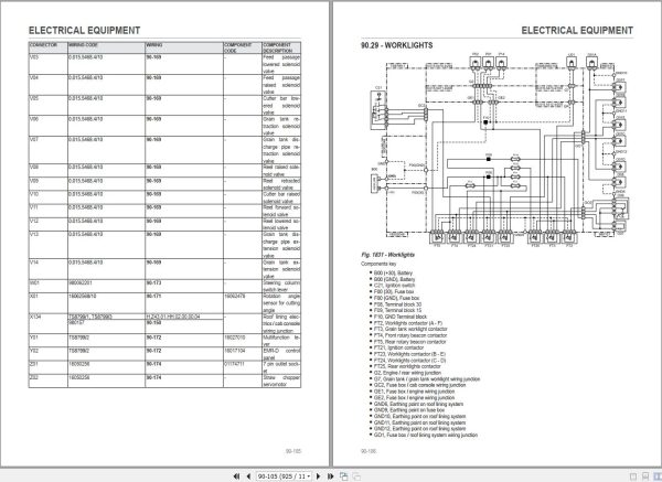
90.28 – Wiring Looms And Components Index
90.29 – Worklights
90.30 – Windscreen Wiper
90.31 – Balance
90.32 – Solenoid Valves
90.33 – Electric Motors
90.34 – Grain Tank Sensors
90.35 – Attachment
90.36 – Feed Passage Sensors
90.37 – Lights
90.38 – Air Conditioner
90.39 – Front Wiring Loom – 0.015.5469.4/20
90.40 – Battery Positive Lead – 16002049
90.41 – Battery Negative Lead – 16002046
90.42 – Cab Console Wiring – Ts8799/1, Ts8799/3
90.43 – Engine Interface Wiring – 0.015.5475.4/10
90.44 – Engine Wiring Loom – 0.015.5471.4/20
90.45 – Fuse Box Wiring – 0.015.5312.4/20
90.46 – Grain Tank Wiring Loom – 0.015.5473.4/10
90.47 – Charge Circuit Wiring Loom – 0.015.5464.4/10
90.48 – Attachment Electrical Socket Wiring Loom – 0.015.5466.4/10
90.49 – Rear Number Plate Light Wiring Loom – 16056728/10
90.50 – Coolant Temperature Sensor Wiring Loom – 16062294
90.51 – Balance Wiring – 0.015.5467.4/10
90.52 – Electric Motor Wiring Loom – 0.015.5472.4/10
90.53 – Returns Elevator Emergency Switch – 16050268
90.54 – Roof Lining Electrics Wiring Loom – 980157
90.55 – Balance Wiring Loom – 16052333
90.56 – Cab Roof Worklights Wiring Loom – 980060
90.57 – Air Conditioner Wiring Loom – 540465
90.58 – Air Conditioning System Filter-Dryer Wiring Loom – 16050276
90.59 – Rear Wiring – 0.015.5470.4/20
90.60 – Rear Lateral Light Wiring Loom – 16013845
90.61 – Sieve Lighting Wiring Loom – 16050274
90.62 – Side Lights Wiring Loom – 16056753
90.63 – Side Lights Wiring Loom – 16056731/10
90.64 – Feed Passage Reversing Device Wiring Loom – 16062550
90.65 – Feed Passage Sensors Wiring Loom – 0.015.5465.4 /10
90.66 – Chassis Wiring Loom – 0.015.5474.4/10
90.67 – Grain Tank Worklight Wiring Loom – 16062565/10
90.68 – Solenoid Valves Assembly Wiring Loom – 0.015.5468.4/10
90.69 – Cutting Table Cutting Angle Sensor Wiring Loom – 16062568/10
90.70 – Multifunction Lever Wiring Loom – Ts8799/2
90.71 – Steering Column Switch Wiring Loom – 980062201
90.72 – Straw Chopper Wiring Loom – 16050256
100 – Threshing Unit
100.1 – Threshing Section Clutch
100.2 – Assembling The Threshing Drum
100.3 – Concave Electrical Adjustment
100.4 – Concave Suspension, De-Awner Covers
100.5 – Assembling The Reversing Drum
100.6 – Threshing Drum Speed Variator
100.7 – Installing The Variator Pulley
100.8 – Variator Adjustment
100.9 – Changing The Variator Belt
100.10 – Dust Plate And Gaskets On Threshing Section
100.11 – Threshing Drum Speed Reduction
100.12 – Turbo Separator
100.13 – Installing The Maize Concave
100.14 – Threshing Drum – Maize Harvesting, Welding Of Threshing Drum Beater Bars
110 – Cleaning Unit
110.1 – Straw Walkers Drive
110.2 – Straw Walker Transmission Adjustment
110.3 – Straw Walker Supports Assembly
110.4 – Assembling Straw Walker Shafts And Straw Walker
110.5 – Installation Of Straw Walker Rakes
110.6 – Sieve Crankshaft
110.7 – Stepped Gain Pan With Removable Segments
110.8 – Stepped Grain Pan And Sieve Box With Transmission
110.9 – Fan Speed Variator
110.10 – Fan – Shroud
110.11 – Tailings Elevator (Returns Elevator)
110.12 – Electric Sieve Adjustment
120 – Grain Tank – Elevator
120.1 – Grain Elevator With Elevator Head
120.2 – Elevator Head, Speed Control
120.3 – Elevator Head For Grain Tank Extension
120.4 – Grain Tank Clutch
120.5 – Emptying The Grain Tank
120.6 – Grain Discharge System
120.7 – Bevel Gear In Elbow Pipe
120.8 – Support For Grain Tank Pipe, Block
120.9 – Grain Tank Level Sensors
130 – Cutting Table
130.1 – Controls Diagram, Speed
130.2 – Cutting Table Drive, Reel Variator
130.3 – Slipping Clutch For Intake Auger And Reel
130.4 – Intake Auger
130.5 – Intake Auger Settings
130.6 – Blade Mechanism – 80 Mm Stroke
130.7 – Blade Mechanism – 85 Mm Stroke
130.8 – Blade Control Transmission Check; Changing The Blade
130.9 – Assembly Of Potentiometer For Cutting Table Adjustment
130.10 – Connectors Assignment, 13 Pin Socket
130.11 – Diagram Of Pipelines And Connection Diagram For Hydraulic System On Rape Header
130.12 – Rape Header Drive
140 – Attachments And Accessories
140.1 – Straw Guide Plate Adjustment
140.2 – Straw Chopper V-Belt Clutch
140.3 – Speed Monitoring
140.4 – Conversion Of Straw Chopper For Threshing Maize And Sunflowers
140.5 – Lining For Straw Hood
140.6 – Electrically Driven Movement From Straw Guide Plate To Straw Chopper
REALEASE :
REALEASE :

REALEASE :
REALEASE :

REALEASE :
14.03.2022
REALEASE :
14.03.2022
REALEASE :
REALEASE :
REALEASE :
REALEASE :
REALEASE :

REALEASE :
01.07.2020
REALEASE :
01.07.2020

REALEASE :
01.08.2020
REALEASE :
01.08.2020
 Automotive - Heavy Equipment - Truck & Bus - Forklift - Crane