
1 ITEMVIEW CART

Total: 300.00
Expert Support
Full Speed
100% Working
80 USD
Contents:
0 – Introduction
0.1 – Introduction
0.1.1 – Safety notes
0.1.2 – General safety rules
0.1.3 – Safety precautions for removal and refitting operations
0.1.4 – Lifting instructions
0.1.5 – Tightening torques
0.1.6 – Threadlockers, adhesives, sealants and lubricants
0.1.7 – Conversion factors10 – Technical characteristics
10.1 – Transmission
10.1.1 – Transmission
10.1.2 – Rear PTO
10.2 – Rear axle
10.2.1 – Rear axle
10.3 – Front axle
10.3.1 – Front axle
10.3.2 – Front axle
10.3.3 – Front axle
10.4 – Hydraulic system
10.4.1 – Hydraulic system
10.4.2 – Ancillary utility distributor – 8-way version
10.4.3 – Ancillary utility distributor – 10-way version
10.4.4 – Variable displacement pump
10.4.5 – Variable displacement pump (60cc/rev)
10.4.6 – Steering gear pump
10.4.7 – Ancillary utility distributor – Version for front lift
10.4.8 – Power steering
10.4.9 – Braking system
10.4.10 – Master cylinder
10.4.11 – Servo-brake valve for front axle
10.4.12 – Hydraulic trailer braking system – Italy version
10.4.13 – Hydraulic trailer braking system – Export version
10.4.14 – Compressor
10.4.15 – Pressure limiting valve
10.4.16 – Trailer air braking valve (2-way)
10.4.17 – Trailer air braking valve (1-way)
10.4.18 – Trailer air brake boost solenoid valve
10.4.19 – Trailer parking brake control solenoid valve
10.4.20 – Quick pressure release valve
10.4.21 – Hydraulic front axle suspension
10.4.22 – Front suspension assembly / INTEGRALL20 – Calibrations and electronic diagnosis
20.1 – Diagnostic instrument
20.1.1 – All Round Tester (ART®)
20.1.2 – Introduction
20.1.3 – Safety instructions
20.1.4 – General preferences
20.1.5 – General preferences – Availability
20.1.6 – General preferences – Licence purchasing
20.1.7 – General preferences – Access and communication
20.1.8 – Program handling – General communication access
20.1.9 – Program handling – Programstart and home screen
20.1.10 – Program handling – Main menu
20.1.11 – Program handling – Configuration
20.1.12 – Program handling – Error memory
20.1.13 – Program handling – Dataset management
20.1.14 – Program handling – Offline Viewer
20.1.15 – Program handling – Usecases EMR4
20.1.16 – Program handling – Usecases EMR3
20.1.17 – Fault location
20.1.18 – FAQ
20.2 – Putting the tractor into service
20.2.1 – Commissioning – Introduction (HLHP software version SC155AE)
20.2.2 – Monitor – Main menu
20.2.3 – Monitor – Transmission
20.2.4 – Monitor – PTO
20.2.5 – Monitor – ASM
20.2.6 – Monitor – Lift
20.2.7 – Monitor – Suspension
20.2.8 – Monitor – System
20.2.9 – Monitor – CAN
20.2.10 – Monitor – Distributors
20.2.11 – Monitor – Engine
20.2.12 – Monitor – Air conditioner
20.2.13 – Monitor – Park Brake
20.2.14 – Calibration – Main menu
20.2.15 – Calibration – Transmission
20.2.16 – Calibration – PTO
20.2.17 – Calibration – ASM
20.2.18 – Calibration – Lift
20.2.19 – Calibration – Suspension
20.2.20 – Calibration – System
20.2.21 – Calibration – Distributor
20.2.22 – Calibration – Engine
20.2.23 – Calibration – A/C system
20.2.24 – Calibration – Park Brake
20.2.25 – Calibration – Agrosky
20.2.26 – Calibration – MR-D cab
20.2.27 – Test – Main menu
20.2.28 – Test – Transmission
20.2.29 – Test – PTO
20.2.30 – Test – ASM
20.2.31 – Test – Lift
20.2.32 – Test – Suspension
20.2.33 – Test – System
20.2.34 – Test – CAN
20.2.35 – Test – Distributors
20.2.36 – Test – Engine
20.2.37 – Test – A/C system
20.2.38 – Alarms menu
20.2.39 – PLA2 armrest diagnostics (software version 1.0.00)
20.3 – ECU alarms
20.3.1 – Alarm list for battery isolator (BDC)
20.3.2 – Engine alarms
20.3.3 – Transmission alarms
20.3.4 – Armrest alarms
20.3.5 – Electrohydraulic control valve alarms
20.3.6 – HLHP alarms
20.3.7 – Climate control alarms
20.3.8 – EPB Alarms30 – Method of intervention
30.1 – Index Repair instructions
30.1.1 – Repair level III
30.2 – D0 – Transmission
30.2.1 – Pump Drive flange
30.2.2 – Pump Drive flange disassembly
30.2.3 – Adjustment of the bevel gear pair
30.2.4 – Removing the rear pinion
30.2.5 – PTO clutch
30.2.6 – Disassembly of the PTO clutch.
30.2.7 – PTO unit
30.2.8 – PTO assembly disassembly
30.2.9 – Adjustment of selector sleeve position
30.2.10 – Adjusting the handbrake device
30.2.11 – Disassembly of the transmission
30.2.12 – Removal of transmission
30.2.13 – Disassembly of the clutch control block
30.2.14 – Disassembly of the system control block
30.2.15 – Disassembly of the pump
30.2.16 – Separation of the transmission halves
30.2.17 – Disassembly of the intermediate housing
30.2.18 – Disassembly of the front wheel drive
30.2.19 – Disassembly of clutch KV/KR and double gear
30.2.20 – Disassembly of the output gear
30.2.21 – Disassembly of the input shaft (hydrostatic unit)
30.2.22 – Disassembly of the central shaft (clutch KV/KR)
30.2.23 – Disassembly of the intermediate gear
30.2.24 – Disassembly of the multi-disk brake (BG)
30.2.25 – Disassembly of the drum selector gear (planetary transmission)
30.2.26 – Disassembly of the ring gear P4/BG and clutch K3/K4
30.2.27 – Disassembly of the central shaft
30.2.28 – Disassembly of the hydrostatic unit
30.2.29 – Reassembly of the transmission
30.2.30 – Reassembly of the clutch housing
30.2.31 – Reassembly of the hydrostatic unit
30.2.32 – Reassembly of the drum selector gear (planetary transmission)
30.2.33 – Reassembly of the central shaft
30.2.34 – Reassembly of ring gear P4/BG
30.2.35 – Reassembly of the multi disk brake (BG)
30.2.36 – Reassembly of the intermediate housing
30.2.37 – Reassembly of the input shaft (hydrostatic unit)
30.2.38 – Reassembly of the intermediate gear
30.2.39 – Reassembly of the central shaft (clutch KV/KR)
30.2.40 – Reassembly of the output gear
30.2.41 – Reassembly of the pump
30.2.42 – Reassembly of double gear and clucth KV/KR
30.2.43 – Reassembly of the front wheel drive
30.2.44 – Joining of the preassembled transmission halves
30.2.45 – Setting of the axial play drum selector gear/quill shaft (KV/KR) – Axial play= 0.20 … 0.40 mm
30.2.46 – Setting of the axial play of the KV/KR bearing – Axial play= 0.00 … 0.08 mm
30.2.47 – Setting of the axial play of the double gear bearing – Axial play= 0.00 … 0.08 mm
30.2.48 – Setting of the axial play of the front wheel drive – Axial play= 0.025 … 0.1 mm
30.2.49 – Reassembly of the system control block
30.2.50 – Reassembly of the clutch control block
30.2.51 – Reassembly of the speed and inductive sensor
30.3 – E0 – Rear axle
30.3.1 – Right-left hand rear axle
30.3.2 – Disassembly of LH/RH rear axle
30.3.3 – Disassembly of the planet carrier
30.3.4 – Rear differential
30.3.5 – Disassembly of the rear differential
30.3.6 – Rear axle brake assemblies and brake discs
30.3.7 – Renewal of brake seals
30.4 – F0 – Front axle
30.4.1 – Troubleshooting
30.4.2 – Toe-in/steering angle/assembly tests
30.4.3 – Steering cylinders assembly
30.4.4 – Axle shaft assembly
30.4.5 – Differential assembly – carrier
30.4.6 – Differential disassembly – ML version
30.4.7 – Differential disassembly – LS version
30.4.8 – Checking the bevel gear pair
30.4.9 – Flange assembly
30.4.10 – Bevel pinion assembly
30.4.11 – Planetary reduction gear assembly
30.4.12 – Planetary reduction gear assembly
30.4.13 – Wheel hub assembly
30.4.14 – Brake assembly
30.5 – H0 – Hydraulic system
30.5.1 – LS variable displacement pump filter
30.5.2 – Tightening the hydraulic power steering unit fastener screws
30.6 – L0 – Electrical system
30.6.1 – Steering position sensor assembly
30.6.2 – Tightening torques for nuts and bolts of electrical connections
30.7 – R0 – Rear lift
30.7.1 – Lift cylinders
30.7.2 – Position sensor bush
30.7.3 – Lift draft sensor
30.7.4 – Lift position sensor
30.7.5 – Calibrating position sensor
30.7.6 – Tightening lift mount fasteners
30.8 – S0 – Wheels
30.8.1 – Wheel rim to hub screws and nuts tightening torques40 – Wiring diagrams
40.1 – Introduction
40.1.1 – Introduction
40.1.2 – Basic electronics for mechanics (1/2)
40.1.3 – Basic electronics for mechanics (2/2)
40.1.4 – Electrical and electronic components (1/2)
40.1.5 – Electrical and electronic components (2/2)
40.2 – Components
40.2.1 – 2.8519.155.0 – HLHP control unit
40.2.2 – 2.8519.154.0 – Transmission control unit
40.2.3 – 02959607 – Engine control unit
40.2.4 – A – Starting and charging
40.2.5 – B – Fuses
40.2.6 – C – Grounds
40.2.7 – D – Intermediate connections
40.2.8 – E – On-board instruments and visual and audible indicators
40.2.9 – F – External lights
40.2.10 – G – Interior lights
40.2.11 – H – Electrical and manual controls
40.2.12 – I – Circuit breakers
40.2.13 – J – Relays
40.2.14 – K – Sensors and transmitters
40.2.15 – L – Electromagnets and solenoid valves
40.2.16 – M – Electrical/electronic devices, flasher units and timers
40.2.17 – N – Electric motors and actuators
40.2.18 – O – Resistors, rheostats, diodes and diode boards
40.2.19 – P – Various services
40.2.20 – R – Diagnostics
40.2.21 – T – Power supply points (+15 o +30)
40.3 – Systems
40.3.1 – S001 – Electronic engine governor
40.3.2 – S002 – Starter
40.3.3 – S003 – Preheating
40.3.4 – S004 – AdBlue
40.3.5 – S005 – Transmission
40.3.6 – S005A – Transmission – Version with performance steering
40.3.7 – S006 – Front axle suspension
40.3.8 – S007 – Instrument panel
40.3.9 – S008 – Lights – Version without front lift
40.3.10 – S009 – Lights – Version with front lift
40.3.11 – S010 – Turn indicators
40.3.12 – S011 – Work lights
40.3.13 – S012 – ISO 11786
40.3.14 – S013 – Manual air conditioner
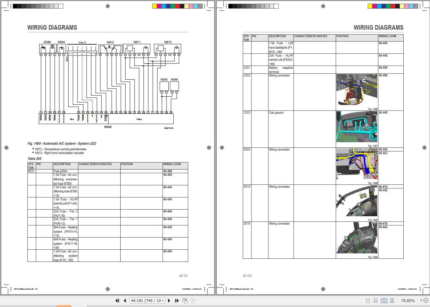
40.3.15 – S014 – Automatic air conditioning
40.3.16 – S015 – +15 Positives
40.3.17 – S016 – +30 Positives
40.3.18 – S017 – CAN BUS Line – Standard version
40.3.19 – S017A – Visual guidance Can Bus line – Version without ISO11783
40.3.20 – S017B – ISO11783 Can Bus line
40.3.21 – S017C – ISO11783 Can Bus line – Version with visual guidance
40.3.22 – S017D – ISO11783 Can Bus line – Version with assisted steering
40.3.23 – S017E – ISO11783 Can Bus line – Version with performance steering
40.3.24 – S018 – PTO
40.3.25 – S019 – Front and rear lifts
40.3.26 – S020 – Brakes
40.3.27 – S021 – Hydraulic trailer braking
40.3.28 – S022 – Hydraulic distributors
40.3.29 – S023 – Windscreen wipers
40.3.30 – S024 – Radio
40.3.31 – S025 – Accessories
40.3.32 – S026 – Diagnostics
40.3.33 – S027 – Agrosky – Version with visual guidance, without ISO11783
40.3.34 – S028 – ISO11783
40.3.35 – S028A – ISO11783 – Version with visual guidance
40.3.36 – S028B – ISO11783 – Version with assisted steering
40.3.37 – S028C – ISO11783 – Version with performance steering
40.3.38 – S029 – Lights – Version without front lift (U.S.A.)
40.3.39 – S030 – Lights – Version with front lift (U.S.A.)
40.3.40 – S031 – Turn indicators (U.S.A.)
40.3.41 – S032 – Work lights (U.S.A.)
40.3.42 – S033 – +15 Positives (U.S.A.)
40.3.43 – S034 – +30 Positives (U.S.A.)
40.3.44 – S035 – PTO (USA)
40.3.45 – S036 – Brakes (USA)
40.4 – Wiring harnesses
40.4.1 – 0.012.2018.4/20 – License plate light
40.4.2 – 0.012.4029.4/30 – Battery negative
40.4.3 – 0.014.0007.4/20 – Lights selector switch
40.4.4 – 0.015.3974.4/10 – Front axle suspension
40.4.5 – 0.015.5429.4/20 – Front lift control
40.4.6 – 0.016.0642.4/20 – Rear LH lower work light on cab – Xenon version
40.4.7 – 0.016.0642.4/20 – Rear RH lower work light on cab – Xenon version
40.4.8 – 0.016.0650.4/10 – RH front supplementary work light on arm – Xenon version
40.4.9 – 0.016.0650.4/10 – LH front supplementary work light on arm – Xenon version
40.4.10 – 0.016.8489.4 – Trailer air brake boost solenoid valve
40.4.11 – 0.016.8489.4 – Trailer parking brake solenoid valve – Version with air braking
40.4.12 – 0.017.0164.4 – Rear camera
40.4.13 – 0.017.0496.4/10 – Supplementary RH front work light on arm
40.4.14 – 0.017.0496.4/10 – Supplementary LH front work light on arm
40.4.15 – 0.017.0497.4/20 – Rear RH lower work light on cab
40.4.16 – 0.017.0497.4/20 – Rear LH lower work light on cab
40.4.17 – 0.017.8425.4 – Rear trailer socket
40.4.18 – 0.017.8426.4 – Rear trailer socket (U.S.A.)
40.4.19 – 0.017.8887.4/10 – ISO 11783 – Front line
40.4.20 – 0.017.9761.4/10 – Distributors D6-D7
40.4.21 – 0.018.2800.4 – Hydraulic braking
40.4.22 – 0.018.8803.4 – Battery positive terminal
40.4.23 – 0.018.9843.4/10 – ISO 11783 – Rear line
40.4.24 – 0.019.0059.4/20 – Roof
40.4.25 – 0.019.2378.4/30 – LH mudguard
40.4.26 – 0.019.2378.4/30 – RH mudguard
40.4.27 – 0.019.2379.4/20 – Front RH lower work lights on cab
40.4.28 – 0.019.2379.4/20 – Front LH lower work lights on cab
40.4.29 – 0.019.2380.4/20 – Hazard warning lights switch (USA)
40.4.30 – 0.019.2571.4/10 – ISO 11786
40.4.31 – 0.019.2617.4/60 – ISO 11783 – Cab line
40.4.32 – 0.019.3652.4 – Side instrument panel
40.4.33 – 0.019.3655.4 – RH transmission
40.4.34 – 0.019.3656.4 – LH transmission
40.4.35 – 0.019.3658.4/20 – Agrosky solenoid valve
40.4.36 – 0.019.3659.4/10 – On-board monitor – Armrest
40.4.37 – 0.019.4559.4/10 – Rear service work light
40.4.38 – 0.019.4585.4 – Fuses and relays
40.4.39 – 0.019.4688.4/10 – Front top work lights on cab
40.4.40 – 0.019.4689.4/20 – RH rear work lights on cab roof
40.4.41 – 0.019.4689.4/20 – Rear work lights on cab roof
40.4.42 – 0.019.4848.4/10 – Manual A/C system
40.4.43 – 0.019.4913.4/10 – Front top work lights on cab – LED version
40.4.44 – 0.019.4914.4/20 – RH rear work lights on cab roof – LED version
40.4.45 – 0.019.4914.4/20 – LH rear work lights on cab roof – LED version
40.4.46 – 0.019.5311.4/10 – Automatic A/C system interface
40.4.47 – 0.019.5518.4/10 – Automatic A/C system
40.4.48 – 0.019.9825.4/10 – Agrosky antenna (Assisted Steering)
40.4.49 – 0.019.9826.4/20 – Agrosky
40.4.50 – 0.019.9827.4/10 – Front work lights on cab roof – LED version with Agrosky
40.4.51 – 0.019.9828.4/10 – Front work lights on cab roof – Version with Agrosky
40.4.52 – 0.019.9829.4/10 – Agrosky antenna (Visual guidance)
40.4.53 – 0.020.1005.4 – Solenoid valve for condenser
40.4.54 – 0.020.1026.4/10 – LH front supplementary work light on arm – USA version
40.4.55 – 0.020.1026.4/10 – RH front supplementary work light on arm – USA version
40.4.56 – 0.020.2565.4 – AdBlue
40.4.57 – 0.020.3254.4 – Front LH lower work lights on cab
40.4.58 – 0.020.3254.4 – Front RH lower work lights on cab
40.4.59 – 0.020.3427.4 – Viscostatic fan
40.4.60 – 0.020.3530.4 – Engine cowl
40.4.61 – 0.900.0816.0 – Front PTO
40.4.62 – 0.900.2092.9 – ZF transmission
40.4.63 – 04217216 – Preheating relay power supply
40.4.64 – 04218383 – Preheating
40.4.65 – 04436707 – LH rotating beacon
40.4.66 – 04219348 – Engine
40.4.67 – 04436707 – RH rotating beacon
40.4.68 – 04502029 – Fuel injectors
REALEASE :
REALEASE :
REALEASE :
REALEASE :
REALEASE :
REALEASE :
REALEASE :

REALEASE :
REALEASE :

REALEASE :
01.08.2020
REALEASE :
01.08.2020

REALEASE :
14.03.2022
REALEASE :
14.03.2022

REALEASE :
01.07.2020
REALEASE :
01.07.2020
 Automotive - Heavy Equipment - Truck & Bus - Forklift - Crane