
1 ITEMVIEW CART

Total: 40.00


Expert Support
Full Speed
100% Working
50 USD
Contents:
Introduction
1.1. Introduction
1.2. Tightening torques for nuts and bolts of Deutz engines
1.3. Tightening torques for nuts and bolts of electrical connections
1.4. Pump tightening torques
1.5. Installation of solenoid valves and cartridge valves
1.6. Installation of quick couplers
Technical characteristics
1.1. Engine
1.1.1. Components of the 2012 2V UPS engine
1.1.2. Test data and settings
1.1.3. Tightening requirements 2012 2V UPS engine
1.2. Transmission
1.2.1. Transmission
1.2.2. Input clutch and hydrostatic unit
1.2.3. Mechanical speed variator and “Work” and “Transport” clutches
1.2.4. Shuttle unit
1.2.5. Bevel pinion and range gearbox assembly
1.2.6. Electrohydraulic four-wheel drive engagement assembly
1.2.7. Differential unit
1.2.8. Brakes and rear axle assembly
1.2.9. Rear PTO
1.2.10. PTO clutch assembly
1.2.11. 2-speed PTO and groundspeed PTO
1.2.12. 3-speed PTO
1.3. Front axle
1.3.1. Front axle
1.4. Bodywork – Cab – Platform
1.4.1. General introduction to the A/C system
1.4.2. Changes of the state of matter
1.4.3. Air conditioning system – General system
1.4.4. Compressor
1.4.5. Condenser
1.4.6. Filter-drier
1.4.7. Expansion valve
1.4.8. Evaporator
1.4.9. Air conditioning system – Diagnostics
1.4.10. Charging the A/C system
1.5. Hydraulic system
1.5.1. Hydraulic system
1.5.2. Hydraulic steering, brakes and services diagram – Standard version
1.5.3. Hydraulic steering, brakes and services diagram – Version with front PTO
1.5.4. Steering and services circuit pressure ports
1.5.5. Hydraulic lift and remote control valve circuit diagram – Basic version
1.5.6. Hydraulic lift and remote control valve circuit diagram – 8-way version with hydraulic trailer braking and supplementary pump
1.5.7. Hydraulic lift and auxiliary services spool valve circuit diagram – 8-way version with hydraulic trailer braking and front lift
Calibrations and electronic diagnosis
1.1. Diagnostic tools
1.1.1. Position of ECUs and diagnostic instruments
1.1.2. All Round Tester (ART®)
1.1.3. ART® – Diagnostic socket connection
1.1.4. SDF Analyser
1.1.5. SDF Analyser – Diagnostic socket connection
1.1.6. SERDIA 2000 level III” software
1.1.7. SERDIA – Diagnostic socket connection
1.2. Diagnostic tool screens
1.2.1. ECU interrogation
1.2.2. ART® transmission screen pages – Introduction
1.2.3. ART® transmission screen pages – Tester structure
1.2.4. ART® transmission screen pages – Tester structure
1.2.5. ART® transmission screen pages – Monitor
1.2.6. ART® transmission screen pages – Monitor -> Transmission
1.2.7. ART® transmission screen pages – Calibration
1.2.8. ART® transmission screen pages – Test
1.2.9. ART® transmission screen pages – Test -> Transmission
1.2.10. ART® transmission screen pages – Alarms
1.2.11. ART® transmission screen pages – Alarms -> HLHP Alarms
1.2.12. ART® transmission screen pages – Alarms -> Engine Alarms
1.2.13. ART® transmission screen pages – Alarms -> Clearing
1.3. Commissioning and calibrating the tractor
1.3.1. Digital Instrument Calibration
1.3.2. Wheel constants
1.3.3. Commissioning – Purpose of the document
1.3.4. Commissioning – Instruments and information required
1.3.5. Commissioning – Description of the commissioning procedure
1.3.6. Commissioning – Basic procedure
1.3.7. Commissioning – EEPROM Re-initialisation
1.3.8. Commissioning – Model configuration
1.3.9. Commissioning – Model options selection
1.3.10. Commissioning – Clutch pedal calibration
1.3.11. Commissioning – Hand throttle and pedal accelerator calibration
1.3.12. Commissioning – Front PTO configuration
1.3.13. Commissioning – Entering the rear PTO calibration value
1.3.14. Commissioning – Electrohydraulic spool valves configuration
1.3.15. Commissioning – ASM sensor calibration
1.3.16. Commissioning – Calibration of the draft sensor
1.3.17. Commissioning – Rear lift calibration
1.3.18. Commissioning – Hydrostatic unit automatic calibration
1.3.19. Commissioning – Automatic calibration of the Work and Reverse clutches
1.3.20. Commissioning – Manual calibration of the Work and Reverse clutches
1.3.21. Commissioning – Hydrostatic unit manual calibration
1.3.22. Commissioning – Rear PTO automatic calibration
1.3.23. ART Transmission screen pages – Introduction
1.3.24. ART Transmission screen pages – Tester structure
1.3.25. ART Transmission screen pages – Main Menu
1.3.26. ART Transmission screen pages – Monitor Screen Pages
1.3.27. ART Transmission screen pages – Calibration Screen Pages
1.3.28. ART Transmission screen pages – Test Screen Pages
1.3.29. ART Transmission screen pages – Alarm Screen Pages
1.3.30. PTO operation
1.3.31. Electrohydraulic spool valves
1.4. ECU alarms
1.4.1. ECU alarms
1.4.2. Alarms – Emergency operating mode
1.4.3. Engine alarms
1.4.4. Transmission alarms
1.4.5. Instrument panel alarms
1.4.6. HLHP alarms
1.4.7. Lift alarms
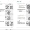
Method of intervention
1.1. Tools for engine disassembly and reassembly
1.2. Workshop tools for engine disassembly and reassembly
1.3. Workshop tools for transmission disassembly and reassembly
1.4. B0 – Engine
1.4.1. Compression test
1.4.2. Assembly and disassembly of the engine on the assembly stand
1.4.3. Adjustment of valve clearance
1.4.4. Removal and refitting of the rocker arms and pedestals
1.4.5. Disassemble and complete the rocker and support, check
1.4.6. Disassembly and assembly of the cylinder head
1.4.7. Grinding the cylinder head seal surface
1.4.8. Measuring piston protrusion
1.4.9. Valve assembly and disassembly
1.4.10. Valve check
1.4.11. Check the valve guide
1.4.12. Replacing the valve guide (oversized – cast)
1.4.13. Check the valve residual
1.4.14. Replacing the lined valve seat (oversized)
1.4.15. Check the endfloat of the crankshaft
1.4.16. Check the crankshaft
1.4.17. Replace the crankshaft O-ring (flywheel end)
1.4.18. Replacing the crankshaft O-ring (opposite end to flywheel)
1.4.19. Check the connecting rod drum
1.4.20. Fitting and removing piston pin bush
1.4.21. Assembly and disassembly of the crankshaft
1.4.22. Fitting and removing counterweight shafts, checking
1.4.23. Disassembly and assembly of the piston and connecting rod drum
1.4.24. Check the piston
1.4.25. Check the piston rings and piston grooves
1.4.26. Assembly and disassembly of piston cooling nozzles
1.4.27. Removal and refitting of the crankcase breather
1.4.28. Check the cylinder
1.4.29. Removal and refitting of the front cover (opposite end to flywheel)
1.4.30. Disassembly and assembly of the connector box
1.4.31. Fitting and removing the camshaft bearings, checking
1.4.32. Disassembly and assembly of the gear case cover
1.4.33. Assembly and disassembly of the camshaft
1.4.34. Check the camshaft
1.4.35. Removal and refitting of the rotation device
1.4.36. Removing and fitting the V-belt pulley
1.4.37. Fitting, removing, checking and setting adjuster rod
1.4.38. Removal and refitting of the heater
1.4.39. Removal and refitting of the turbocharger
1.4.40. Removal and refitting of the charge air duct
1.4.41. Fitting and removing injection pump
1.4.42. Determine the thickness of the shim (engine without injection advance variator)
1.4.43. Determine the thickness of the shim (engine with injection advance variator)
1.4.44. Determination of the overall dimensions of the injection pump (engine without the injection advance variator)
1.4.45. Determination of the overall dimensions of the injection pump (engine with the injection advance variator)
1.4.46. Fitting and removing injection valves
1.4.47. Checking the injection valves
1.4.48. Removal and refitting of the fuel lift pump
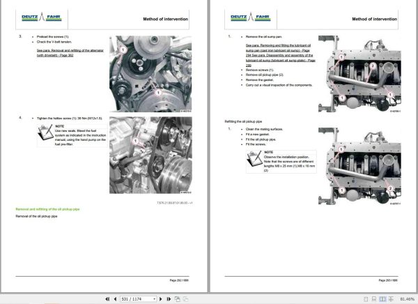
1.4.49. Removal and refitting of the oil pickup pipe
1.4.50. Removing and fitting the lubricant oil sump pan (cast iron lubricant oil sump)
1.4.51. Disassembly and assembly of the lubricant oil sump (lubricant oil sump-plate)
1.4.52. Removal and refitting of the oil cooler
1.4.53. Disassembly and assembly of the oil radiator housing
1.4.54. Removal and refitting of the oil pressure switch
1.4.55. Removal and refitting of the water pump
1.4.56. Testing the thermostat (after removal)
1.4.57. Removal and refitting of the thermostat
1.4.58. Removal and assembly of the fan support
1.4.59. Removal and refitting of the fan support
1.4.60. Removal and refitting of the flywheel
1.4.61. Replacing the starter motor ring gear on the flywheel
1.5. C0 – Engine accessories
1.5.1. Removing and fitting the engine governor
1.5.2. Removal and refitting of the exhaust manifold
1.5.3. Removal and refitting of the fuel filter head
1.5.4. Assembly and disassembly of the temperature sender
1.5.5. Removal and refitting the engine block
1.5.6. Removal and refitting of the alternator (with drivebelt)
1.5.7. Disassembly and assembly of the starter
1.6. D0 – Transmission
1.6.1. Sealants application
1.6.2. Transmission wiring
1.6.3. Hydraulic system components
1.6.4. INPUT clutch disc replacement
1.6.5. INPUT unit
1.6.6. INPUT unit disassembly
1.6.7. Hydrostatic unit
1.6.8. Hydrostatic unit pipes
1.6.9. Complete front casing (with INPUT unit and hydrostatic unit)
1.6.10. Replacing the variator input shaft bearings
1.6.11. Replacing the WORK and TRANSPORT clutch assemblies (with the intermediate casing installed)
1.6.12. Intermediate casing
1.6.13. Variator unit input gear assembly
1.6.14. Disassembling the variator input gear unit
1.6.15. WORK and TRANSPORT clutch-planetary reduction gearbox assembly
1.6.16. Planetary reduction gearbox for the WORK and TRANSPORT clutches
1.6.17. Disassembling the WORK and TRANSPORT planetary reduction gearbox
1.6.18. Disassembling the WORK and TRANSPORT clutches
1.6.19. REVERSE clutch-planetary reduction unit
1.6.20. Disassembling the REVERSE planetary reduction unit
1.6.21. Pump unit flange
1.6.22. Disassembling the pump support flange
1.6.23. Speed range gear shafts
1.6.24. Disassembling the range gear control lever
1.6.25. Disassembling the transfer case gear
1.6.26. PTO engagement clutch
1.6.27. PTO casing
1.6.28. Disassembling the PTO casing
1.6.29. Disassembling PTO engagement clutch
1.6.30. PTO drive shaft
1.6.31. PTO speed selection lever
1.6.32. PTO driven shaft
1.6.33. Disassembling the PTO driven shaft
1.6.34. P.T.O. output shaft. – Nut torquing
1.6.35. Differential pinion
1.6.36. Disassembling the differential pinion
1.6.37. Disassembling the HD (Heavy Duty) range gear
1.6.38. 4WD shaft
1.6.39. Disassembling the dual traction shaft
1.7. E0 – Rear axle
1.7.1. Axle casing
1.7.2. Adjustment of supports
1.7.3. Wheel mount disassembly
1.7.4. Disassembling the rear differential case
1.7.5. Removing rear differential
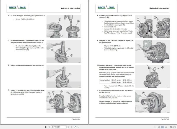
1.7.6. Controlling and adjusting the clearance of the teeth on the pinion and the differential crown wheel
1.7.7. Rear differential
1.7.8. Park brake unit
1.7.9. Disassembling the park brake unit
1.8. F0 – Front axle
1.8.1. Steering knuckle housing and half-shaft
1.8.2. Front brake discs
1.8.3. Adjustment of steering knuckle housing and axle shaft
1.8.4. Pinion and differential assembly
1.8.5. Planetary reduction gear
1.8.6. Disassembly of the final drive unit
1.8.7. Disassembly of the differential locking device
1.8.8. Differential pinion unit disassembly
1.8.9. Adjustment of differential preload and pinion-crown wheel backlash
1.8.10. Pinion positioning and preload adjustment
1.8.11. Disassembly of the differential
1.9. G0 – Bodywork – Cab – Platform
1.9.1. Adjustment of Bowden cable
1.10. H0 – Hydraulic system
1.10.1. Spool valves
1.10.2. Trailer air braking system operating control – Export D Version
1.10.3. Supplementary pump
1.10.4. TANDEM pump
1.10.5. Power steering pump
1.10.6. Transfer pump
1.11. L0 – Electrical system
1.11.1. Steering angle sensor
1.12. M0 – Front PTO
1.12.1. Clutch pack end float values check
1.12.2. Cylindrical roller bearings
1.13. R0 – Rear lift
1.13.1. Stabiliser tie-rod carrier
1.13.2. Internal lever setscrew
1.13.3. Lift
Wiring diagrams
1.1. Introduction
1.1.1. Introduction
1.1.2. Basic electronics for mechanics (1/2)
1.1.3. Basic electronics for mechanics (2/2)
1.1.4. Electrical and electronic components (1/2)
1.1.5. Electrical and electronic components (2/2)
1.2. Components
1.2.1. A – Starting and charging
1.2.2. B – Fuses
1.2.3. C – Earths
1.2.4. D – Intermediate connections
1.2.5. E – On-board instruments and visual and audible indicators
1.2.6. F – External lights
1.2.7. G – Interior lights
1.2.8. H – Electrical and manual controls
1.2.9. I – Circuit breakers
1.2.10. J – Relays
1.2.11. K – Sensors and transmitters
1.2.12. L – Electromagnets and solenoid valves
1.2.13. M – Electrical/electronic devices, flasher units and timers
1.2.14. N – Electric motors and actuators
1.2.15. O – Resistors and rheostats
1.2.16. P – Various services
1.2.17. Q – Safety devices
1.2.18. R – Diagnostics
1.2.19. 04213097 – Engine ECU
1.2.20. 2.8339.269.0/20 – Instrument panel
1.2.21. 2.8519.101.0/20 – HLHP ECU
1.3. Systems
1.3.1. S001 – Starting and preheating
1.3.2. S002 – Electronic engine governor
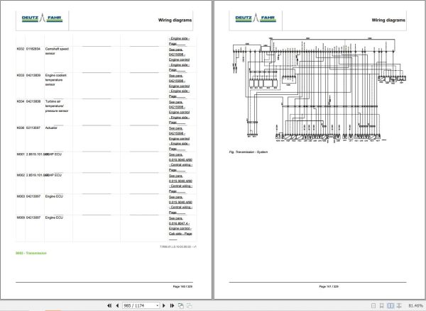
1.3.3. S003 – Transmission
1.3.4. S004 – Instrument panel
1.3.5. S005 – Steering column switch unit lights – Version without front lift
1.3.6. S006 – Steering column switch unit lights – Version with front lift
1.3.7. S007 – Worklights – Version without front lift
1.3.8. S008 – Worklights – Version with front lift
1.3.9. S009 – Manual air conditioner
1.3.10. S010 – Heating
1.3.11. S011 – Power supply (+15)
1.3.12. S012 – Power supply (+30) – Version with front battery
1.3.13. S013 – Power supply (+30) – Version with lateral battery
1.3.14. S014 – Negatives
1.3.15. S015 – CAN BUS
1.3.16. S016 – PTO – Version without front PTO
1.3.17. S017 – PTO – Version with front PTO
1.3.18. S018 – Brakes
1.3.19. S019 – Spool valves and lifts
1.3.20. S020 – Windscreen wipers
1.3.21. S021 – Diagnostics – Accessories
1.4. Wiring harnesses
1.4.1. 0.017.1063.4 – Cab earth
1.4.2. 0.017.9016.4/10 – Battery negative – Version with front battery
1.4.3. 0.017.8922.4/10 – Battery negative – Version with lateral battery
1.4.4. 0.017.0474.4 – Battery positive
1.4.5. 0.015.1983.4/10 – Platform 1 power supply
1.4.6. 0.015.1983.4/10 – Platform 2 power supply
1.4.7. 0.015.1983.4/10 – Roof power supply
1.4.8. 0.014.9195.4/20 – Preheating
1.4.9. 0.014.8666.4/30 – Hood lights
1.4.10. 0.013.4085.4/20 – RH hood worklights
1.4.11. 0.013.4085.4/20 – LH hood worklights
1.4.12. 0.016.2000.4/20 – Engine – Version with front battery
1.4.13. 0.016.2001.4/10 – Engine – Version with lateral battery
1.4.14. 04215098 – Engine control – Engine side
1.4.15. 0.016.8047.4 – Engine control – Cab side
1.4.16. 0.012.2756.3 – Front PTO solenoid valve
1.4.17. 0.011.3797.3 – SBA
1.4.18. 0.015.9040.4/60 – Central wiring
1.4.19. 0.017.8385.4/10 – Side console wiring
1.4.20. 0.010.6468.3/10 – Pneumatic seat
1.4.21. 0.017.2347.4/5159.4 – Multifunction control lever
1.4.22. 0.014.9570.4/10 – ISO 11786
1.4.23. 0.015.9041.4/50 – Transmission
1.4.24. 0.015.9043.4/40 – Transmission solenoid valves
1.4.25. 0.016.0373.4/30 – Cab power supply
1.4.26. 0.015.6272.4/40 – Roof
1.4.27. 0.015.7266.4/40 – Air conditioning condenser fan
1.4.28. 0.016.0664.4 – Front lights
1.4.29. 04411923.4 – Lower RH headlight
1.4.30. 04411923.4 – Lower LH headlight
1.4.31. 0.014.3927.4/40 – Supplementary RH worklight on arm
1.4.32. 0.014.3927.4/40 – Supplementary LH worklight on arm
1.4.33. 0.011.3597.3 – Windscreen wiper
1.4.34. 0.013.6327.4 – RH side rotating beacon
1.4.35. 0.013.6327.4 – LH side rotating beacon
1.4.36. 0.016.1001.4/20 – Hydraulic trailer braking valve
1.4.37. 0.014.1645.4/10 – Compressed air pressure sensor

REALEASE :
01.07.2020
REALEASE :
01.07.2020

REALEASE :
01.08.2020
REALEASE :
01.08.2020
REALEASE :
REALEASE :
REALEASE :

REALEASE :
14.03.2022
REALEASE :
14.03.2022
REALEASE :
REALEASE :

REALEASE :
REALEASE :
REALEASE :
REALEASE :
Automotive - Heavy Equipment - Truck & Bus - Forklift - Crane