
8 ITEMSVIEW CART


Total: 515.00

Expert Support
Full Speed
100% Working
100 USD
Contents:
0 – INTRODUCTION
0.1 – Introduction
0.1.1 – Safety notes
0.1.2 – General safety
0.1.3 – Precautions to use during performance of the work
0.1.4 – Lifting instructions
0.1.5 – Tightening torques
0.1.6 – Thread lock, adhesive, sealant and lubrication materials
0.1.7 – Unit of measurement conversion table
0.2 – Tightening torques
0.2.1 – General information
0.2.2 – Tightening classes and categories
0.2.3 – Coefficient of friction
0.2.4 – Tightening torques
0.3 – Pump tightening torques
0.3.1 – Installation
0.4 – Wheel rim to hub screws and nuts tightening torques
0.5 – Tightening torques for nuts and bolts of electrical connections
0.5.1 – Standard tightening torques
0.5.2 – Battery terminal tightening torques
0.5.3 – Starter motor tightening torques
0.5.4 – Alternator tightening torques
0.6 – Installation of solenoid valves and cartridge valves
0.6.1 – Installation
0.6.2 – Solenoid valve tightening torques
0.6.3 – Cartridge valve tightening torques
0.7 – Installation of quick couplers
0.7.1 – Table of tightening torques
0.8 – One-way valves
0.8.1 – Purpose
0.8.2 – Assembly
0.9 – Fixing the steering wheel
0.9.1 – Purpose
0.9.2 – Installation
0.10 – Spool valves
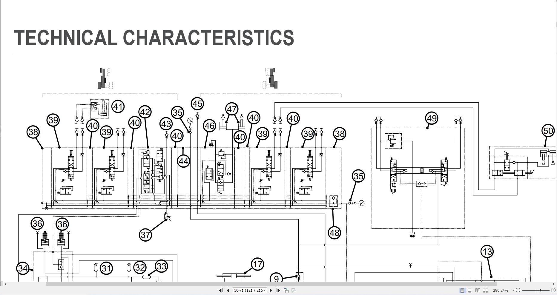
0.10.1 – Tightening tie rods of spool valves type SB23LS10 – TECHNICAL CHARACTERISTICS
10.1 – Engine accessories
10.1.1 – AdBlue® technical characteristics
10.2 – Transmission
10.2.1 – Rear PTO
10.2.2 – Transmission (ZF TPT)
10.3 – Front axle
10.3.1 – Front axle (6185 AGROTRON -> WSXCB60200LD10000)
10.3.2 – Front axle (6155 AGROTRON -> WSXCA40200LD10000, 6165 AGROTRON -> WSXCA70200LD10000, 6175 AGROTRON -> WSXCB00200LD10000)
10.3.3 – General characteristics (6155 AGROTRON -> WSXCA40200LD10000, 6165 AGROTRON -> WSXCA70200LD10000, 6175 AGROTRON -> WSXCB00200LD10000)
10.4 – Bodywork – Cab – Platform
10.4.1 – Brake master cylinders
10.4.2 – General introduction to the A/C system
10.4.3 – Air conditioning system
10.4.4 – Air conditioning system
10.4.5 – Air conditioning system – Diagnostics
10.4.6 – Compressor
10.4.7 – Condenser
10.4.8 – Filter-dryer
10.4.9 – Expansion valve
10.5 – Hydraulic system
10.5.1 – Brake logic block
10.5.2 – Bistable valve block
10.5.3 – Basic hydraulic circuit (“Mother Regulation”)
10.5.4 – Hydraulic circuit, full house version (“Mother Regulation”)
10.5.5 – Hydraulic circuit, optional version 1 (“Mother Regulation”)
10.5.6 – Hydraulic circuit, optional version 2 (“Mother Regulation”)
10.5.7 – STEERING/TRANSMISSION circuit, full house version
10.5.8 – STEERING/TRANSMISSION circuit, optional version
10.5.9 – STEERING/TRANSMISSION circuit, base version
10.5.10 – Ancillary utility distributor – 4-way mechanically controlled version
10.5.11 – Ancillary utility distributor – Front distributor and lift module
10.5.12 – Ancillary utility distributor 8-way electronically controlled version
10.5.13 – Ancillary utility distributor 8-way mechanically controlled version
10.5.14 – Rear lift distributor
10.5.15 – Delivery line filter – ancillaries/SAC circuit
10.5.16 – LS variable displacement pump filter
10.5.17 – Front suspension system – INTEGRAL accumulators
10.5.18 – Hydraulic power steering (OSPD)
10.5.19 – LS hydraulic power steering (OSPEDC)
10.5.20 – Braking system
10.5.21 – 45 cc variable displacement pump
10.5.22 – Variable displacement pump (60cc/rev)
10.5.23 – Gear pump
10.5.24 – Master cylinder
10.5.25 – Hydraulic front axle suspension
10.5.26 – Trailer braking valve – EXPORT version
10.5.27 – Trailer braking valve – ITALY version
10.5.28 – Priority valve
10.6 – Front PTO
10.6.1 – Front PTO20 – CALIBRATIONS AND ELECTRONIC DIAGNOSIS
20.1 – Diagnostic tools
20.1.1 – Diagnostic port
20.1.2 – SDF SUITE
20.1.3 – Serdia 2010
20.2 – Diagnostic tool screens
20.2.1 – Monitor – Main menu
20.2.2 – Monitor – Transmission
20.2.3 – Monitor – PTO
20.2.4 – Monitor – ASM
20.2.5 – Monitor – Lift
20.2.6 – Monitor – Suspension
20.2.7 – Monitor – System
20.2.8 – Monitor – CAN
20.2.9 – Monitor – Distributors
20.2.10 – Monitor – Engine
20.2.11 – Monitor – Air conditioner
20.2.12 – Monitor – Park Brake
20.2.13 – Test – Main menu
20.2.14 – Test – Transmission
20.2.15 – Test – PTO
20.2.16 – ASM test
20.2.17 – Test – Lift
20.2.18 – Test – Suspension
20.2.19 – Test – System
20.2.20 – Test – Distributors
20.2.21 – Test – Engine
20.2.22 – Test – A/C system
20.2.23 – Alarms menu
20.2.24 – PLA2 armrest diagnostics (software version 1.0.00)
20.3 – Commissioning and calibrating the tractor
20.3.1 – SECU re-initialisation
20.3.2 – End of line procedure
20.3.3 – Commissioning – Transmission
20.3.4 – Commissioning – PTO
20.3.5 – Commissioning – ASM
20.3.6 – Commissioning – Lift
20.3.7 – Commissioning – Suspension
20.3.8 – Commissioning – System
20.3.9 – Commissioning – Distributors
20.3.10 – Commissioning – Engines
20.3.11 – Commissioning – AC system
20.3.12 – Commissioning – Agrosky
20.3.13 – Commissioning – Introduction (SECU software version SW GGr1401)
20.3.14 – Calibration Agrosky Systems
20.4 – ECU alarms
20.4.1 – Engine alarms
20.4.2 – Fan alarms
20.4.3 – Transmission alarms
20.4.4 – Armrest alarms
20.4.5 – HLHP alarms
20.4.6 – BODY alarms
20.4.7 – AC system alarms
20.4.8 – EPB Alarms
20.4.9 – Electrohydraulic control valve alarms
20.4.10 – AGROSKY alarms
20.5 – Software management
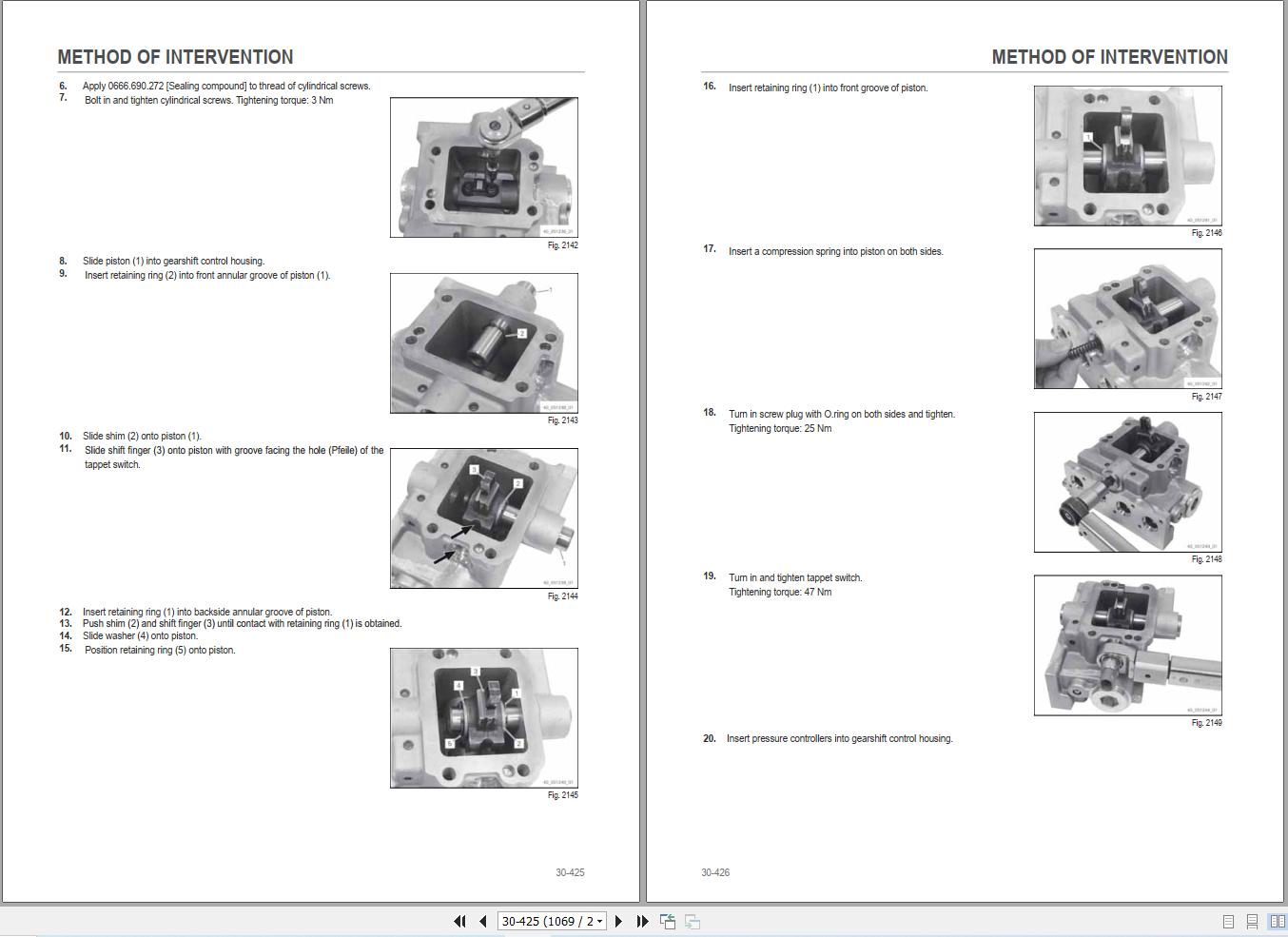
20.5.1 – Engine dataset upgrade30 – METHOD OF INTERVENTION
30.1 – Tools for engine disassembly and reassembly
30.1.1 – Commercially available tools
30.2 – Workshop tools for engine disassembly and reassembly (Lv.2)
30.2.1 – Workshop tools for engine disassembly and reassembly (Lv.2)
30.3 – Workshop tools for disassembly and reassembly
30.4 – B0 – Engine
30.4.1 – Complete engine (1/2) (B0.00.01)
30.4.2 – Complete engine (2/2)
30.4.3 – Engine – Separating from the transmission (1/2) (B0.00.02)
30.4.4 – Engine – Separating from the transmission (2/2)
30.4.5 – Air conditioning compressor belt (B0.02.04)
30.4.6 – Removal and refitting of the crankcase breather
30.4.7 – Replacing the crankshaft O-ring (opposite end to flywheel)
30.4.8 – Disassembling/assembling crankshaft wear sleeve (side opposite flywheel)
30.4.9 – Disassembling and assembling the front cover (fixing elements)
30.4.10 – Topping up with oil
30.4.11 – Removing and fitting lubricant oil sump (heavy version)
30.4.12 – Fitting and removing the lubricant oil filter
30.4.13 – Removing and fitting the V-belt pulley
30.4.14 – Removing and fitting the torsional vibration damper
30.4.15 – Removing and fitting the flywheel (fixing elements)
30.4.16 – Adapter ring (V-belt pulley)
30.4.17 – Compression test
30.4.18 – Removing and fitting the cylinder head cover
30.4.19 – Replace the crankshaft O-ring (flywheel end)
30.4.20 – Check and adjust valve clearances
30.4.21 – Disassembling and assembling the oil cooler
30.4.22 – Removing and refitting lubricant oil cooler housing (fastener elements)
30.4.23 – Closing components
30.4.24 – Closing components
30.4.25 – Coolant pipe
30.4.26 – Coolant pipe (lubricant oil cooler – cylinder head)
30.4.27 – Disassembly and assembly of the fuel control unit (fastening elements)
30.4.28 – Fitting and removing the high pressure pump (fastener elements)
30.4.29 – Disassembling and assembling the injector (1600 bar injection system)
30.4.30 – Disassembling and assembling the rail system (1600 bar injection system)
30.4.31 – Fuel lines (fuel delivery pump, fuel control unit, high pressure pump, rail, cylinder head)
30.4.32 – Fuel lines (fuel delivery pump, fuel filter, fuel control unit, rail, cylinder head)
30.4.33 – Vibration damper (installation position)
30.4.34 – Removing and fitting the charge air duct
30.4.35 – Pressure transducer (exhaust back-pressure).
30.4.36 – Removing and fitting the coolant pump (fastener elements)
30.4.37 – Removing and refitting adapter (coolant pump – thermostat housing)
30.4.38 – Actuating elements
30.4.39 – Removing and fitting the thermostat
30.4.40 – Testing the thermostat (after removal)
30.4.41 – Removal and installation of the thermostat housing
30.4.42 – Closing components
30.4.43 – Closing components
30.4.44 – Removing and refitting idler roller (poly-V-belt, level 1)
30.4.45 – Belt drive (belt tensioner)
30.4.46 – Removal and installation of the exhaust pipe (auxiliaries)
30.4.47 – Disassembling and assembling the exhaust manifold
30.4.48 – Disassembling and assembling the butterfly valves
30.4.49 – Disassembling and assembling the Venturi pipe
30.4.50 – Removing and fitting the mount (exhaust gas recovery)
30.4.51 – Removing and fitting connector pipes (cylinder head – radiator – exhaust gas recirculation)
30.4.52 – Pipe (exhaust pipe – pressure transducer)
30.4.53 – Disassembling and assembling the radiator
30.4.54 – Removing and fitting turbocharger (turbocharger with regulator)
30.4.55 – Removing and fitting the lubricant oil pipe (turbocharger without regulator)
30.4.56 – Removing and fitting the lubricant oil pipe (turbocharger with regulator)
30.4.57 – Removing and fitting the lubricant oil return pipe (lower) (turbocharger with/without regulator)
30.4.58 – Removing and fitting the lubricant oil return pipe (upper) (turbocharger with regulator)
30.4.59 – Removing and fitting the lubricant oil return pipe (upper) (turbocharger with regulator)
30.4.60 – Removing and fitting pipe (crankcase – regulator unit – thermostat housing)
30.4.61 – Fitting compensator (turbocharger with/without regulator)
30.4.62 – Removing and fitting the belt tensioner (ribbed V-belt, level 2)
30.4.63 – Removing and refitting alternator (poly-V-belt, level 2)
30.4.64 – Disassembly and assembly of the alternator (ribbed V-belt, level 1).
30.4.65 – Disassembling and assembling the V-belt pulley (with locking cone)
30.4.66 – Fitting and removing the console (ribbed V-belt, level 1).
30.4.67 – Removing and fitting the mounting console (poly-V-belt, level 2)
30.4.68 – Removing and refitting idler roller (poly-V-belt, level 2)
30.4.69 – Installation and removal of the rotation device
30.4.70 – Installation and removal of the rotation device (torsional vibration damper)
30.4.71 – Disassembly and assembly of the connector box
30.4.72 – Covering case
30.4.73 – Connector cable (turbocharger without regulator – charge air intercooler)
30.4.74 – Connector cable (turbocharger with regulator – charge air intercooler)
30.4.75 – Removing and fitting the charge air manifold
30.4.76 – Charge air radiator
30.4.77 – Removing and fitting the regulator unit
30.4.78 – Removing and fitting the mixer pipe
30.4.79 – Removing and fitting the butterfly valve filter
30.4.80 – Removing and refitting the diesel particulate filter
30.4.81 – Removing and refitting refrigerant compressor
30.4.82 – Blanking elements (PTO-B)
30.4.83 – Engine oil sump (B0.00.03)
30.4.84 – Blanking elements (crankcase, PTO-A)
30.5 – C0 – Engine accessories
30.5.1 – Removing and fitting the fuel filter head
30.5.2 – Disassembling and assembling the fuel delivery pump (fastener elements)
30.5.3 – Fuel filter
30.5.4 – Air pressure/temperature sender (intake air)
30.5.5 – Removing and fitting the fan mount (fastener elements)
30.5.6 – Assembly and disassembly of the temperature sender
30.5.7 – Removing and fitting the pressure transducer
30.5.8 – Fastener elements (starter)
30.5.9 – Shield plate (starter)
30.5.10 – Removing and fitting the crankshaft speed sensor (fastener elements)
30.5.11 – Removal and refitting of the camshaft speed sensor
30.5.12 – Fastener elements (wiring bundle)
30.5.13 – Fastening elements
30.5.14 – Connector cable (relay – alternator)
30.5.15 – Connector cable (relay – heater)
30.5.16 – Removing and fitting the heater
30.5.17 – Temperature sender (exhaust gas)
30.5.18 – Engine coolant replacement (C0.01.02)
30.5.19 – Fan (C0.01.05)
30.5.20 – Bloccaggio grani ventola
30.5.21 – Cooler (C0.01.01)
30.5.22 – Complete radiator pack (C0.01.03)
30.5.23 – Compensation tank (C0.01.04)
30.5.24 – Intercooler, gearbox oil and fuel exchangers and condenser (C0.02.02)
30.5.25 – Air filter cartridge (C0.02.01)
30.5.26 – Air filter container
30.5.27 – Fuel pre-filter
30.5.28 – Draining the fuel tanks
30.5.29 – Diesel fuel tank (C0.03.01)
30.5.30 – Fuel tank mount
30.5.31 – Auxiliary tank (C0.03.02)
30.5.32 – Auxiliary fuel tank mount
30.5.33 – Air compressor
30.5.34 – Air compressor disassembly
30.5.35 – Starter motor
30.5.36 – DOC (diesel oxidation catalyst) catalytic converter
30.5.37 – Disassembling the DOC (diesel oxidation catalyst) catalytic converter
30.5.38 – Exhaust silencer (C0.06.01)
30.5.39 – AdBlue tank (C0.06.04)
30.5.40 – AdBlue pump module
30.5.41 – AdBlue Connection Backflow – Inlet pipes
30.5.42 – AdBlue 2 way solenoid valve
30.6 – D0 – Transmission
30.6.1 – Workshop Equipment
30.6.2 – Dismantling transmission housing
30.6.3 – Assembling clutch housing
30.6.4 – Assembling transmission housing
30.6.5 – Draining oil
30.6.6 – Separating rear axle from main transmission
30.6.7 – Removing input shaft
30.6.8 – Removing clutch housing from transmission housing and dismantling it
30.6.9 – Mounting clutch housing to transmission housing
30.6.10 – Installing input shaft
30.6.11 – Installing oil supply
30.6.12 – Adjusting crawler gear shift system
30.6.13 – Mounting main transmission to rear axle
30.6.14 – Changing the transmission oil (D0.00.01)
30.6.15 – Front gearbox housing (1/2) (D0.09.01)
30.6.16 – Front gearbox housing (2/2) (D0.09.01)
30.6.17 – Powershift central gearbox housing (D0.00.04)
30.6.18 – Engine-gearbox connector casing (D0.02.01)
30.6.19 – Torsionally flexible coupling and flywheel (D0.05.01)
30.6.20 – Separating the gearbox housing from the rear gearbox housing (D0.00.03)
30.7 – E0 – Rear axle
30.7.1 – Instruction for bleeding the brakes (E0.03.01)
30.8 – F0 – Front axle
30.8.1 – General information (6155 AGROTRON -> WSXCA40200LD10000, 6165 AGROTRON -> WSXCA70200LD10000, 6175 AGROTRON -> WSXCB00200LD10000)
30.8.2 – Safety information (6155 AGROTRON -> WSXCA40200LD10000, 6165 AGROTRON -> WSXCA70200LD10000, 6175 AGROTRON -> WSXCB00200LD10000)
30.8.3 – Special tools (6155 AGROTRON -> WSXCA40200LD10000, 6165 AGROTRON -> WSXCA70200LD10000, 6175 AGROTRON -> WSXCB00200LD10000)
30.8.4 – Troubleshooting (6155 AGROTRON -> WSXCA40200LD10000, 6165 AGROTRON -> WSXCA70200LD10000, 6175 AGROTRON -> WSXCB00200LD10000)
30.8.5 – Front axle (F0.03.01)
30.8.6 – Carrier with rear axle (F0.01.01)
30.8.7 – Front axle carrier
30.8.8 – 4WD shaft cover (6155 AGROTRON -> WSXCA40200LD10000, 6165 AGROTRON -> WSXCA70200LD10000, 6175 AGROTRON -> WSXCB00200LD10000)
30.8.9 – 4WD shaft (F0.04.01)
30.8.10 – Under-sump reinforcement (F0.04.02)
30.8.11 – Pinion seal flange (6155 AGROTRON -> WSXCA40200LD10000, 6165 AGROTRON -> WSXCA70200LD10000, 6175 AGROTRON -> WSXCB00200LD10000)
30.8.12 – Steering cylinder assembly (6155 AGROTRON -> WSXCA40200LD10000, 6165 AGROTRON -> WSXCA70200LD10000, 6175 AGROTRON -> WSXCB00200LD10000)
30.8.13 – Planetary reduction gearbox unit (6155 AGROTRON -> WSXCA40200LD10000, 6165 AGROTRON -> WSXCA70200LD10000, 6175 AGROTRON -> WSXCB00200LD10000)
30.8.14 – Wheel hub unit (without service brake) (6155 AGROTRON -> WSXCA40200LD10000, 6165 AGROTRON -> WSXCA70200LD10000, 6175 AGROTRON -> WSXCB00200LD10000)
30.8.15 – Wheel hub and brake assembly (6155 AGROTRON -> WSXCA40200LD10000, 6165 AGROTRON -> WSXCA70200LD10000, 6175 AGROTRON -> WSXCB00200LD10000)
30.8.16 – Beam assembly (6155 AGROTRON -> WSXCA40200LD10000, 6165 AGROTRON -> WSXCA70200LD10000, 6175 AGROTRON -> WSXCB00200LD10000)
30.8.17 – Carrier assembly (6155 AGROTRON -> WSXCA40200LD10000, 6165 AGROTRON -> WSXCA70200LD10000, 6175 AGROTRON -> WSXCB00200LD10000)
30.8.18 – Differential carrier assembly (Limited Slip) (6155 AGROTRON -> WSXCA40200LD10000, 6165 AGROTRON -> WSXCA70200LD10000, 6175 AGROTRON -> WSXCB00200LD10000)
30.8.19 – Differential carrier assembly (Wet Clutch) (6155 AGROTRON -> WSXCA40200LD10000, 6165 AGROTRON -> WSXCA70200LD10000, 6175 AGROTRON -> WSXCB00200LD10000)
30.8.20 – Differential assembly (6155 AGROTRON -> WSXCA40200LD10000, 6165 AGROTRON -> WSXCA70200LD10000, 6175 AGROTRON -> WSXCB00200LD10000)
30.8.21 – Differential assembly (wet clutch) (6155 AGROTRON -> WSXCA40200LD10000, 6165 AGROTRON -> WSXCA70200LD10000, 6175 AGROTRON -> WSXCB00200LD10000)
30.8.22 – Pinion assembly (6155 AGROTRON -> WSXCA40200LD10000, 6165 AGROTRON -> WSXCA70200LD10000, 6175 AGROTRON -> WSXCB00200LD10000)
30.8.23 – Toe-in/steering angle (6155 AGROTRON -> WSXCA40200LD10000, 6165 AGROTRON -> WSXCA70200LD10000, 6175 AGROTRON -> WSXCB00200LD10000)
30.8.24 – Post-assembly tests (6155 AGROTRON -> WSXCA40200LD10000, 6165 AGROTRON -> WSXCA70200LD10000, 6175 AGROTRON -> WSXCB00200LD10000)
30.8.25 – Safety precautions (6185 AGROTRON -> WSXCB60200LD10000)
30.8.26 – Oil Draining Mandatory Procedure (6185 AGROTRON -> WSXCB60200LD10000)
30.8.27 – Pivot brackets (6185 AGROTRON -> WSXCB60200LD10000)
30.8.28 – Stub axle and steering sensor (6185 AGROTRON -> WSXCB60200LD10000)
30.8.29 – Steering cylinders (6185 AGROTRON -> WSXCB60200LD10000)
30.8.30 – Differential assembly (6185 AGROTRON -> WSXCB60200LD10000)
30.8.31 – Conical pinion (6185 AGROTRON -> WSXCB60200LD10000)
30.8.32 – Planetary reduction gearbox and steering knuckle housing (6185 AGROTRON -> WSXCB60200LD10000)
30.9 – G0 – Bodywork – Cab – Platform
30.9.1 – Cab (G0.03.01)
30.9.2 – Right hand cab access steps (G0.03.03)
30.9.3 – Engine hood (G0.01.01)
30.9.4 – Battery mount (G0.01.04)
30.9.5 – Front mudguards (G0.04.01)
30.9.6 – Mat (G0.04.02)
30.9.7 – Under-seat mat
30.9.8 – Right hand rear pillar cover
30.9.9 – Left hand rear pillar cover
30.9.10 – Right hand control console (G0.06.01)
30.9.11 – Left hand console (G0.06.02)
30.9.12 – Instrument cluster (G0.06.04)
30.9.13 – Instrument cluster (G0.06.05)
30.9.14 – Cab roof panel trim (G0.06.07)
30.9.15 – Windscreen wiper electric motor
30.9.16 – Door handle
30.9.17 – Active carbon filter
30.9.18 – Driver seat (G0.08.01)
30.9.19 – Passenger seat
30.9.20 – Empty and charge the air conditioning system (G0.09.01)
30.9.21 – A/C unit (G0.09.03)
30.9.22 – Air conditioning compressor
30.9.23 – A.C. Electronic Control Unit replacement
30.9.24 – Clutch pedal
30.9.25 – Brake pedals
30.9.26 – Electronic throttle control
30.9.27 – Disassembling the electronic throttle control
30.9.28 – Steering wheel (G0.13.01)
30.9.29 – Master cylinder (G0.11.01)
30.9.30 – Steering column
30.9.31 – 939475 – Assembly of gear lever (21/03/13)
30.9.32 – Handbrake adjustment
30.10 – H0 – Hydraulic system
30.10.1 – Hydraulic block for braking system
30.10.2 – “Load Sensing” variable displacement pump (H0.01.03)
30.10.3 – Power steering (H0.02.01)
30.10.4 – Tightening the hydraulic power steering unit fastener screws
30.10.5 – Brake system accumulator
30.10.6 – Front hydraulic distributor
30.10.7 – Disassembly of the rear distributor unit (1/2)
30.10.8 – Disassembly of the rear distributor unit (2/2)
30.10.9 – Front axle suspension solenoid valve block. (H0.04.01)
30.10.10 – Rear ancillary distributor (H0.07.01)
30.10.11 – Brake control valve
30.10.12 – Trailer air braking valves (H0.09.02)
30.10.13 – 939420 – Tie-rod installation on brake valve (27/09/2012)
30.10.14 – Air tanks (H0.09.03)
30.10.15 – Air braking system air filter
30.10.16 – Front lift control valve
30.11 – L0 – Electrical system
30.11.1 – Electronic throttle control sensor
30.11.2 – Front lift position sensor
30.11.3 – Radar
30.11.4 – Inductive position sensor
30.11.5 – Front suspension position sensor
30.11.6 – 35 Bar sensor
30.11.7 – Air filter clogged sensor
30.11.8 – Clutch pedal sensor
30.11.9 – Brake control switch
30.12 – N0 – Front lift
30.12.1 – Front lift (N0.01.01)
30.13 – R0 – Rear lift
30.13.1 – Lift cylinders
30.13.2 – 3-point linkage
30.14 – S0 – Wheels
30.14.1 – Front Wheels (S0.01.01)
30.14.2 – Rear wheels (S0.02.01)
30.15 – V0 – Ballast – towing hitches
30.15.1 – Tow hook (V0.02.01)
30.16 – V1 – AFTERMARKET KITS
30.16.1 – Installation of the cab pillar filter frames kit (p.n. 9.AB386.91.0)
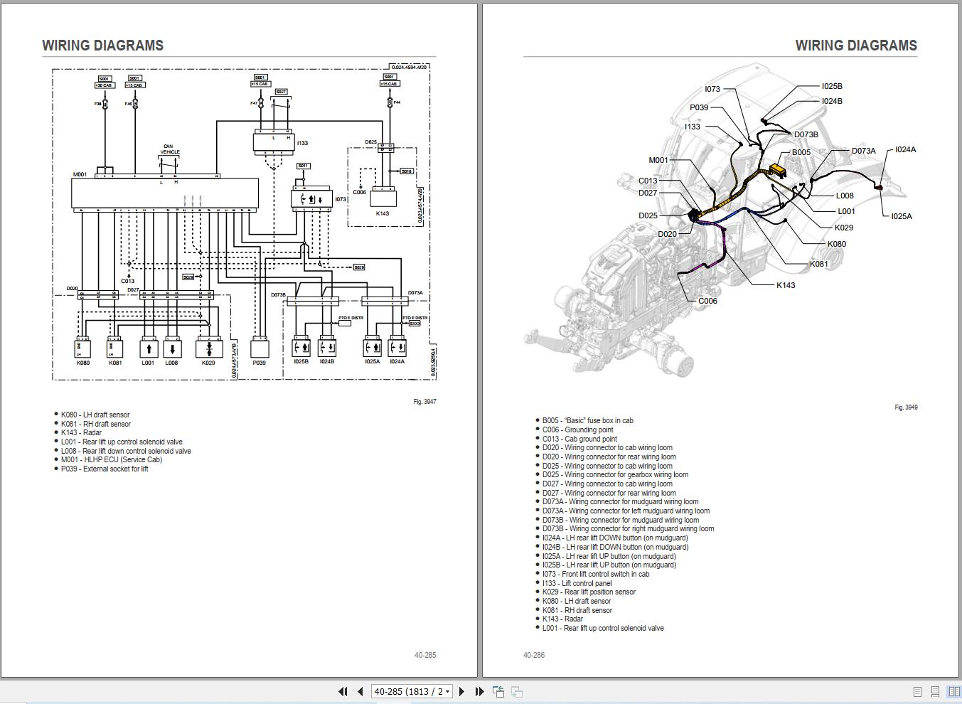
30.16.2 – Installation of the connector’s cover kit40 – WIRING DIAGRAMS
40.1 – Introduction
40.1.1 – Introduction
40.1.2 – Basic electronics for mechanics (1/2)
40.1.3 – Basic electronics for mechanics (2/2)
40.1.4 – Electrical and electronic components (1/2)
40.1.5 – Electrical and electronic components (2/2)
40.2 – Components
40.2.1 – Locations of main ECUs
40.2.2 – HLHP Control unit (Service Controller Cab)
40.2.3 – HLHP Control unit (Service Controller Body)
40.2.4 – Gear box Control unit
40.2.5 – ECU ISO 11786 Control unit
40.2.6 – Engine Control unit
40.2.7 – Remote control unit
40.2.8 – LED worklights control unit
40.2.9 – A – Starting and charging
40.2.10 – B – Fuse box and fuses
40.2.11 – C – Grounds
40.2.12 – D – Intermediate connections
40.2.13 – E – On-board instruments and visual and audible indicators
40.2.14 – F – External lights (rotating beacon)
40.2.15 – G – Interior lights
40.2.16 – H – Manual electrical controls (steering column stalk)
40.2.17 – I – Circuit breakers
40.2.18 – J – Relays
40.2.19 – K – Sensors and transmitters
40.2.20 – L – Electromagnets and solenoid valves
40.2.21 – M – Electrical/electronic devices, Flasher units and Timers
40.2.22 – N – Electric motors and actuators
40.2.23 – O – Resistors and rheostats
40.2.24 – P – Various services
40.2.25 – R – Diagnostics
40.3 – Systems
40.3.1 – S001 – Power
40.3.2 – S002 – Starter
40.3.3 – S003 – Engine control system – version with S2.2 cab
40.3.4 – S003 – Engine control system – version with S1.2 cab
40.3.5 – S004 – Emissions control system – version with S2.2 cab
40.3.6 – S004 – Emissions control system – version with S1.2 cab
40.3.7 – S005 – Front lights
40.3.8 – S006 – Rear work lights
40.3.9 – S007 – Front work lights – Europe version
40.3.10 – S007 – Front work lights – Europe version
40.3.11 – S008 – Sidelights and backlighting – version with S2.2 cab
40.3.12 – S008 – Sidelights and backlighting – version with S1.2 cab
40.3.13 – S009 – Turn indicators – Europe version
40.3.14 – S009 – Turn indicators – USA version
40.3.15 – S010 – Internal lighting – version with “WOLP” lights control panel
40.3.16 – S010 – Internal lighting – version without “WOLP” lights control panel
40.3.17 – S011 – Roof lights – version with “WOLP” lights control panel
40.3.18 – S011 – Roof lights – version without “WOLP” lights control panel
40.3.19 – S012 – Defrost and wipers – version with “WOLP” lights control panel
40.3.20 – S012 – Wipers – version without “WOLP” lights control panel
40.3.21 – S013 – Horn
40.3.22 – S014 – Mirror adjustment
40.3.23 – S015 – Radio
40.3.24 – S016 – Power socket – accessories
40.3.25 – S017 – Air conditioning
40.3.26 – S018 – Front lift – version with S2.2 cab
40.3.27 – S018 – Front lift – version with S1.2 cab
40.3.28 – S019 – Rear lift – version with S2.2 cab
40.3.29 – S019 – Rear lift – version with S1.2 cab
40.3.30 – S020 – Braking system
40.3.31 – S021 – Trailer brake
40.3.32 – S022 – Transmission – version with S2.2 cab
40.3.33 – S022 – Transmission – version with S1.2 cab
40.3.34 – S023 – “ARS” transmission – version with S2.2 cab
40.3.35 – S023 – “ARS” transmission – version with S1.2 cab
40.3.36 – S024 – PTO – version with S2.2 cab
40.3.37 – S024 – PTO – version with S1.2 cab
40.3.38 – S025 – Isobus line – version with S2.2 cab
40.3.39 – S025 – Isobus line – version with S1.2 cab
40.3.40 – S026 – CAN “AUX” line – version with S2.2 cab
40.3.41 – S026 – CAN “AUX” line – version with S1.2 cab
40.3.42 – S027 – CAN “VEHICLE” line – version with S2.2 cab
40.3.43 – S027 – CAN “VEHICLE” line – version with S1.2 cab
40.3.44 – S028 – Agrosky
40.3.45 – S029 – Instrument cluster, work display – version with S2.2 cab
40.3.46 – S029 – Instrument cluster, work display – version with S1.2 cab
40.3.47 – S030 – Front axle – version with S2.2 cab
40.3.48 – S030 – Front axle – version with S1.2 cab
40.3.49 – S031 – Front loader – version with S2.2 cab
40.3.50 – S031 – Front loader – version with S1.2 cab
40.3.51 – S032 – Distributors, provision for solenoid valve module – version with S2.2 cab
40.3.52 – S032 – Distributors, provision for solenoid valve module – version with S1.2 cab
40.4 – Wiring harnesses
40.4.1 – Wire colour reference table
40.4.2 – 0.012.2018.4/20 – License plate lights
40.4.3 – 0.012.4030.4 – Front PTO
40.4.4 – 0.015.4257.4/10 – Front PTO sensor, USA
40.4.5 – 0.016.8489.4 – Engine brake
40.4.6 – 0.017.0496.4/10 – H9 lower front work lights
40.4.7 – 0.017.0497.4/20 – H9 lower rear work lights
40.4.8 – 0.017.8425.4/10 – Trailer socket, EU
40.4.9 – 0.017.8426.4 – Trailer socket, USA
40.4.10 – 0.017.9761.4/10 – Distributors 6/7
40.4.11 – 0.018.2800.4 – Hydraulic trailer braking
40.4.12 – 0.019.2379.4/20 – Front arm lights
40.4.13 – 0.019.2380.4/50 – Hazard warning lights switch (USA)
40.4.14 – 0.019.2571.4/10 – ISO 11786
40.4.15 – 0.019.3659.4/10 – Monitor (Armrest)
40.4.16 – 0.019.4559.4/10 – H9 rear work light (service)
40.4.17 – 0.019.4689.4/20 – H9 roof work lights
40.4.18 – 0.019.4914.4/20 – LED work lights for cab roof
40.4.19 – 0.019.5311.4/10 – Automatic A/C system
40.4.20 – 0.019.9825.4/10 – Antenna – Inertial SRC40
40.4.21 – 0.019.9829.4/20 – Antenna – Agrosky SR10
40.4.22 – 0.020.1009.4 – Front lights on arm (USA)
40.4.23 – 0.020.1026.4/10 – Front turn indicators and lower front work lights (USA)
40.4.24 – 0.020.8190.4 – Semi-automatic shift system (ARS)
40.4.25 – 0.020.8862.4/10 – Roof (for versions with “wolp” light control panel)
40.4.26 – 0.021.0490.4 – ABS socket for trailer
40.4.27 – 0.021.1028.4/10 – Agrosky Adapter
40.4.28 – 0.021.5509.4 – Rear screen defrost
40.4.29 – 0.021.8291.4 – Front LED work lights
40.4.30 – 0.021.8334.4 – LED rear lights
40.4.31 – 0.023.9007.4 – Front wiring loom
40.4.32 – 0.023.9008.4/10 – Cowl
40.4.33 – 0.023.9202.4/10 – Front axle steering sensor (Dana)
40.4.34 – 0.023.9203.4/10 – Front axle steering sensor (Carraro – Agrosky)
40.4.35 – 0.023.9204.4 – Electrohydraulic steering (Agrosky)
40.4.36 – 0.023.9205.4 – Electrohydraulic controls
40.4.37 – 0.023.9243.4/20 – Front ISOBUS socket
40.4.38 – 0.023.9244.4/20 – Rear ISOBUS socket
40.4.39 – 0.023.9245.4 – Front axle steering sensor (Carraro – Basic)
40.4.40 – 0.023.9248.4 – Viscostatic fan
40.4.41 – 0.023.9250.4 – Rear mudguards
40.4.42 – Engine
40.4.43 – 0.023.9582.4/10 – LED work lights for cab roof
40.4.44 – 0.023.9583.4/10 – H9 work lights for cab roof
40.4.45 – 0.024.3197.4/10 – Front axle
40.4.46 – 0.024.4566.4/10 – “Basic” lower fuse box
40.4.47 – 0.024.4567.4/10 – “Plus” supplementary lower fuse box
40.4.48 – 0.024.4569.4 – Roof (for versions without “wolp” light control panel)
40.4.49 – 0.024.4570.4/10 – Battery wiring
40.4.50 – 0.024.4573.4/10 – Rear wiring loom
40.4.51 – 0.024.4574.4/20 – Gearbox
40.4.52 – 0.024.4575.4/20 – “Basic S2.2” cab
40.4.53 – 0.024.4577.4 – “Plus S2.2” cab
40.4.54 – 0.024.4579.4/20 – “basic S1.2” cab
40.4.55 – 0.024.4582.4/10 – “Plus S1.2” cab
40.4.56 – 0.024.4613.4/10 – “Full 1” supplementary lower fuse box
40.4.57 – 0.024.4614.4 – Jump start terminal board
40.4.58 – 0.024.4621.4 – Work lights and rotating beacon switches
40.4.59 – 0.024.4622.4/20 – “Full 2” supplementary lower fuse box
40.4.60 – 0.024.4632.4/20 – Engine brake and ABS socket
40.4.61 – 0.024.4703.4 – “Wolp” lights control panel
40.4.62 – 0.024.5401.4/10 – Front loader
40.4.63 – 0.024.5402.4/10 – Isobus and Agrosky wiring loom (cab S2.2)
40.4.64 – 0.024.5403.4/10 – Isobus and Agrosky wiring loom (cab S1.2)
40.4.65 – 04436707/10 – Flashing beacon
40.4.66 – 04437517 – Outline marker lights 40-617
REALEASE :
REALEASE :
REALEASE :
REALEASE :
REALEASE :
REALEASE :
REALEASE :
REALEASE :
REALEASE :
REALEASE :
 Automotive - Heavy Equipment - Truck & Bus - Forklift - Crane