
0 ITEMSVIEW CART


✓
Expert Support
✓
Full Speed
✓
100% Working
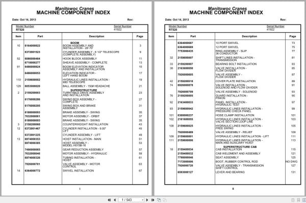
Grove Crane RT520 41922 Parts Manual 2013
Size: 3.96 MB
Format: PDF
Language: English
Brand: Grove
Type of Machine: Crane
Type of Manual: Parts Manual
Model: Grove RT520 Crane
Serial Number: 41922
Publication Date: 2013
Number of Pages: 543 Pages
20 USD
- Description
Description
Contents:
Boom Assembly And Installation – 28′-70′
Cylinder Assembly – 6 1/2″ Telescope (Complete Assembly )
Hook Block Assembly
Sheave Assembly – Complete
Boom Elevation Indicator Assembly And Installation
Elevation Indicator – Left Hand Boom
Hydraulic Lines Installation – Mid Telescope
Ball Assembly – 150# Headache
Turntable Drive Assembly And Installation
Swing Box Assembly – Complete
Swing Box And Brake Assembly
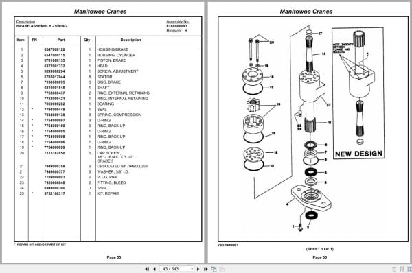
Brake Assembly – Swing
Motor Assembly – Orbit
Counterweight Installation
Cylinder Installation – 9.00” Lift
Cylinder Assembly – Lift
Hoist Installation – Main
Hoist Assembly – Model H015b-16
Gear Reduction Assembly
Motor Assembly – Hydraulic
Tubing Installation – Hoist
Valve Assembly – Motor Control
Swivel Installation
10 Port Swivel
12 Port Swivel
Ring Assembly – Slip 36 Conductor
Shift Lines Installation – Transmission
Bearing Bolt Installation
Valve Installation – Flow Divider
Valve Assembly – Flow Divider
Cover Plate Installation
Valve Installation – Solenoid And Flow Divider
Valve Assembly – Solenoid
Guard Installation – Pinion
Panel Installation – Hydraulic Test
Hydraulic Lines Installation – Pressure Check Panel
Hose Clamp Installation
Hydraulic Lines Installation – Valve Section Loop Line
Hydraulic Lines Installation – Free Swing
Valve Assembly – Relief
Hydraulic Lines Installation – Lift
Hydraulic Lines Installation – Main And Auxiliary Hoist
Cab Installation
Cab Weldment And Assembly
Seat Assembly
Valve Assembly – Transmission Shift Control
Lever And Bearing
Fire Extinguisher Assembly
Instruments And Lights Installation
Electrical System Installation
Fuse And Connector Panel Assembly
Indicator Assembly
Brake Pedal Hydraulic Lines Installation
Heater/Defroster And Fuel Tank Installation
Heater Assembly – Diesel
Extinguisher Installation – Fire
Removable Windshield Storage
Axle Installation –
Axle Assembly
Axle Assembly Hub And Shaft Group
Axle Assembly Differential Carrier Assembly
Axle Assembly Housing Assembly
Axle Assembly Brake Assembly
Cylinder Assembly – 3″ Steer (Complete Assembly )
Outrigger Beam Installation
Cylinder Assembly – Stabilizer
Cylinder Assembly – Extension
Transmission Installation
Transmission Assembly
Transmission Assembly Front Cover And Case Assembly
Transmission Assembly Clutch And Gear Group
Transmission Assembly Axle Disconnect Assembly
Transmission Assembly Low Clutch Assembly
Transmission Assembly Forward Clutch Assembly
Transmission Assembly Reverse And Second Shift
Transmission Assembly Control Valve Assembly
Cylinder Assembly – Air Lockout
Valve Assembly Transmission
Driveline Installation
Driveline Assembly
Reservoir Installation – Hydraulic
Filter Assembly – Oil
Hood Installation – Engine
Fuel Tank Installation
Air Tanks And Valves
Valve Assembly – Check
Actuator Assembly – Air Hydraulic
Transmission And Converter Lines Installation
Air Assembly Schematic
Brake Lines Installation – Hydraulic
Outrigger Valve Installation
Valve Assembly – Outrigger Selector (Complete Assembly )
Valve Assembly – 4 Stack Outrigger Solenoid
Valve Assembly – Sequence
Battery Box Installation
Lockout Installation – Axle
Valve Assembly – Selector
Cylinder Assembly -Lockout
Lights Installation
Battery Installation
Dryer Assembly – Air
Cover Installation – Pump
Radiator Installation
Tool Box Installation
Brake Installation – Parking
Spring Brake Chamber Assembly
Cover Installation – Front
Pad And Storage Installation -Outrigger
Float Assembly – Outrigger
Tow Winch Installation
Hoist Assembly – Model Pd15-77-1
Fenders Assembly And Installation
Valve Installation – Rear Axle Lockout
Indicator Installation – Rear Steer
Supply, Pressure And Return Hydraulic Schematic
Hydraulic Lines Installation – Outrigger
Hydraulic Lines Installation – Front Steer
Hydraulic Lines Installation – Axle Lockout
Lug Nut And Washer Installation
Wiring Diagram
Decal Installation – Rt500 Series
Related Products
-
Grove Crane RT GRT Series Collection Parts Document PDF 43 GB
Original price was: 500.340Current price is: 340. USDThis is an offline spare parts catalog, you need to use this to sell the spare parts and it can help you a little with assembly. It’s from a manufacturer and the best in the world.Hot-32%
REALEASE :
REALEASE :
-
Grove Crane AT ATS Series Collection Parts Document PDF 447 MB
Original price was: 400.70Current price is: 70. USDIf you are a technician, You will need to use this product to repair your vehicleHot-83%
REALEASE :
REALEASE :
-
Grove GMK EPC Spare Part Catalog Manual 2023 PDF EN DE
Original price was: 600.70Current price is: 70. USDThis is an offline spare parts catalog, you need to use this to sell the spare parts and it can help you a little with assembly. It’s from a manufacturer and the best in the world.Hot-88%
REALEASE :
REALEASE :
-
Grove Crane 1.8 Gb YB Series Collection Parts Document PDF
Original price was: 300.70Current price is: 70. USDThis is an offline spare parts catalog, you need to use this to sell the spare parts and it can help you a little with assembly. It’s from a manufacturer and the best in the world.Hot-77%
REALEASE :
REALEASE :
-
Grove RT EPC Spare Parts Catalog Manual 2023 PDF EN
Original price was: 2,000.540Current price is: 540. USDThis is an offline spare parts catalog, you need to use this to sell the spare parts and it can help you a little with assembly. It’s from a manufacturer and the best in the world.Hot-73%
REALEASE :
REALEASE :
-
Grove Parts Document Crane GMK Series Collection 17.1 GB PDF
Original price was: 500.290Current price is: 290. USDThis is an offline spare parts catalog, you need to use this to sell the spare parts and it can help you a little with assembly. It’s from a manufacturer and the best in the world.Hot-42%
REALEASE :
REALEASE :
-
Grove Parts Document Crane 7.82 Gb TM TMS TT TTS Series Collection PDF
Original price was: 400.250Current price is: 250. USDThis is an offline spare parts catalog, you need to use this to sell the spare parts and it can help you a little with assembly. It’s from a manufacturer and the best in the world.Hot-38%
REALEASE :
REALEASE :
-
Grove Crane 2024 Collection Parts Document 72.1 GB PDF
Original price was: 1,200.840Current price is: 840. USDThis is an offline spare parts catalog, you need to use this to sell the spare parts and it can help you a little with assembly. It’s from a manufacturer and the best in the world.Hot-30%
REALEASE :
REALEASE :