
13 ITEMSVIEW CART


Total: 600.00
Expert Support
Full Speed
100% Working
15 USD
Contents:
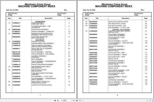
Boom Assembly – 3 Section – 28’-70’
Cylinder Assembly – 6.50’’ Telescope
Hook Block Assembly
Sheave Assembly – Complete
Boom Elevation Indicator Assembly And Installation
Elevation Indicator – Left Hand Boom
Cab Installation
Cab Weldment And Assembly
Front Console Assembly And Control Installation
Pedal And Valve Assembly – Accelerator
Valve Assembly – Control
Valve Assembly – Dual Brake
Control Assembly – Steering
Seat Assembly
Valve Assembly – Transmission Shift Control
Fire Extinguisher Assembly
Instruments And Lights Installation
Electrical System Installation
Fuse And Connector Panel Assembly
Fan Assembly – 12 Volt Cab
Brake Pedal Hydraulic Lines Installation
Cover Plate Installation
Acoustical Installation
Air Lines Installation
Fan Installation – Cab
Control Valve And Linkage Installation
Valve Bank Assembly – 4 Section A-35 Series
Valve Section – Inlet (A-35 Series)
Valve Assembly – Outlet
Valve Assembly – 4-Way Section (A-35 Series)
Valve Sub- Assembly – Relief
Cartridge Assembly – Relief Valve
Valve Section – 4 Way
Valve Assembly – Relief
Relief Valve
Cartridge Assembly
Valve Bank Assembly – One Section A-35 Series
Valve Assembly – Relief 2250 Psi
Valve Bank Assembly – 2 Section A-20 Series
Valve Assembly – Section Inlet (A-20 Series)
Valve Assembly – Section Outlet (A-20 Series)
Valve Installation – Solenoid And Flow Divider
Valve Assembly – Solenoid
Panel Installation – Hydraulic Test
Hydraulic Lines Installation – Pressure Check Panel
Hydraulic Lines Installation – Valve Section Loop Line
Free Swing Hydraulic Schematic
Hydraulic Lines Installation – Lift
Hydraulic Lines Installation – Mid Telescope
Hydraulic Lines Installation – Main And Auxiliary Hoist
Hoist Installation – Main And/Or Auxiliary
Hoist Assembly – Model Ho15b-16
Valve Assembly – Motor Control
Tubing Installation – Hoist
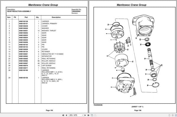
Gear Reduction Assembly
Motor Assembly – Hydraulic
Hose Clamp Installation
Idler Drum Assembly
Turntable Drive Assembly And Installation
Swing Box Assembly – Complete
Swing Box And Brake Assembly
Brake Assembly – Swing
Motor Assembly – Orbit
Counterweight Installation
Cylinder Installation – 9.00’’ Lift
Cylinder Assembly – 9″ Lift
Swivel Installation – Electric/Air/Hydraulic
Swivel Assembly – Hydraulic
Swivel Assembly – Air/Hydraulic
Ring Assembly – Slip 36 Conductor
Valve Installation – Reducing/Relief (Swing)
Valve Assembly – Pressure And Sequence
Brake Valve And Air Tank Installation
Engine Installation – Cat 3208
Filter Assembly – Oil
Filter Assembly – Primary Fuel
Fuel/Water Separater Assembly
Compressor Assembly – Air
Cylinder Assembly – Throttle
Pump Assembly – Steer
Fitting
Exhaust And Air Cleaner Installation
Cleaner Assembly – Air
Hood Installation – Engine
Battery Installation
Radiator Installation
Transmission Installation
Transmission Assembly
Transmission Assembly Front Cover And Case Assembly
Transmission Assembly Clutch And Gear Group
Transmission Assembly Axle Disconnect Assembly
Transmission Assembly Low Clutch Assembly
Transmission Assembly Forward Clutch Assembly
Transmission Assembly Reverse And Second Shift
Transmission Assembly Control Valve Assembly
Cylinder Assembly – Air Lockout
Valve Assembly Transmission
Driveline Installation
Driveline Assembly
Transmission And Converter Lines Installation
Shift Lines Installation – Transmission
Axle Installation – Rear
Axle Assembly – Drive Steer
Axle Assembly – Drive Steer Axle Assembly
Axle Assembly – Drive Steer Differential Carrier Assembly
Axle Assembly – Drive Steer Parking Brake Assembly
Axle Assembly – Drive Steer Planet Spider Assembly
Axle Assembly – Drive Steer Brake Assembly
Cylinder Assembly – 3″ Steer
Tire And Wheel Assembly
Brake Lines Installation – Hydraulic
Lockout Installation – Axle
Valve Assembly – Selector
Cylinder Assembly -Lockout
Valve Installation – Relief (Steer)
Valve Assembly – Relief (See Separate Parts List)
Indicator Installation – Rear Steer
Hydraulic Lines Installation – Front Steer
Hydraulic Lines Installation – Rear Steer
Hydraulic Lines Installation – Axle Lockout
Outrigger Beam Installation
Cylinder Assembly – Stabilizer
Cylinder Assembly – Extension
Hydraulic Lines Installation – Outrigger
Reservoir Installation – Hydraulic
Fuel Tank Installation
Air Tank And Valve Installation
Valve Assembly – Check
Actuator Assembly – Air Hydraulic
Air System Schematic
Lights Installation
Battery Box Installation
Dryer Assembly – Air
Valve Assembly – 4 Stack Outrigger Solenoid
Brake Installation – Parking
Spring Brake Chamber Assembly
Supply, Pressure And Return Hydraulic Schematic
Decal Installation – Rt500 Series
Wiring Diagram
Indicator Assembly
Heater Assembly – Diesel

REALEASE :
REALEASE :

REALEASE :
REALEASE :

REALEASE :
REALEASE :

REALEASE :
REALEASE :

REALEASE :
REALEASE :

REALEASE :
REALEASE :

REALEASE :
REALEASE :

REALEASE :
REALEASE :
 Automotive - Heavy Equipment - Truck & Bus - Forklift - Crane