1 ITEMVIEW CART

Total: 150.00


Expert Support
Full Speed
100% Working
20 USD
Contents:
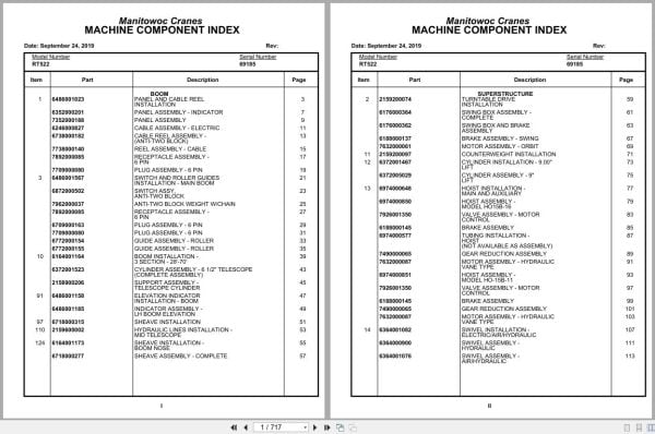
Panel And Cable Reel Installation
Panel Assembly – Indicator
Panel Assembly
Cable Assembly – Electric
Cable Reel Assembly -(Anti-Two Block)
Reel Assembly – Cable
Receptacle Assembly -6 Pin
Plug Assembly – 6 Pin
Switch And Roller Guides Installation – Main Boom
Switch Assy,Anti-Two Block
Anti-Two Block Weight W/Chain
Guide Assembly – Roller
Boom Installation -3 Section – 28′-70′
Cylinder Assembly – 6 1/2″ Telescope(Complete Assembly )
Support Assembly -Telescope Cylinder
Elevation Indicator Installation – Boom
Indicator Assembly -Lh Boom Elevation
Sheave Installation
Hydraulic Lines Installation -Mid Telescope
Sheave Installation -Boom Nose
Sheave Assembly – Complete
Turntable Drive Installation
Swing Box Assembly -Complete
Swing Box And Brake Assembly
Brake Assembly – Swing
Motor Assembly – Orbit
Counterweight Installation
Cylinder Installation – 9.00”Lift
Cylinder Assembly – 9″Lift
Hoist Installation -Main And Auxiliary
Hoist Assembly -Model Ho15b-16
Valve Assembly – Motor Control
Brake Assembly
Tubing Installation -Hoist
Gear Reduction Assembly
Motor Assembly – Hydraulic Vane Type
Hoist Assembly -Model Ho-15b-11
Swivel Installation -Electric/Air/Hydraulic
Swivel Assembly -Hydraulic
Swivel Assembly -Air/Hydraulic
Slip Ring Assembly – 35conductor
Control Valve Andlinkage Installation
Valve Bank Assembly -1 Section
Valve Assembly – Outlet
Valve Section – Inlet(A-35 Series)
Valve Assembly – Relief2250 Psi
Cartridge Assembly
Valve Bank Assembly -2 Section (A-20 Series)
Valve Assembly – Section Inlet (A-20 Series)
Valve Bank Assembly -4 Section (A-35 Series)
Cartridge Assembly -Relief Valve
Valve Assembly – Relief1000 Psi
Bearing Bolt Installation
Lock Installation – Swing
Cable Assy, Swing Lock
Cover Plate Installation
Valve Installation -Reducing/Relief (Swing)
Valve Assembly -Pressure And Sequence
Rotation Indicator Installation
Driver Assembly driver Assembly
Indicator Assembly
Transmitter Assembly
Guard Installation -Pinion
Switch Installation -Remote Cranking Pump
Panel Installation -Hydraulic Test
Hydraulic Lines Installation -Pressure Check Panel
Idler Drum And Cable Follower Installation
Cable Follower
Idler Drum Assembly
Hose Clamp Installation
Hydraulic Lines Installation -Free Swing
Hydraulic Lines Installation – Lift
Hydraulic Lines Installation -Main And Auxiliary Hoist
Pivot Shaft Installation -Boom
Idler Drum Installation
Cab Installation
Cab Assembly
Latch Kit – Door
Valve Assembly – Transmission Shift Control
Pedal And Valve Assembly -Accelerator
Valve Assembly – Control
Valve Assembly – Dual Brake
Valve Assembly -Selector
Instruments And Lights Installation
Harness, Wiring
Extinguisher Installation – Fire
Electrical System Installation – S/S
Panel Assembly – Fuse And Connector
Harness Assembly -Fuse And Connector Panel
Valve Installation -Steer Control
Control Assembly -(W/O Return To Center Steering)
Weatherstrip Installation – Cab
Valve And Pedal Installation – Swing Brake
Valve Assembly -Power Brake
Heater And Defroster Installation – Propane
Heater Assembly – Propane
Seat Installation
Seat Assembly
Fan Installation – Cab Circulating
Fan Assembly – 12 Volt Cab(Complete Assembly )
Wiper Installation -Skylight
Wiper And Washer Installation – Windshield
Air Lines Installation –
Brake Valve And Air Tank Installation
Warning System Installation – Audio/Visual
Grab Rail Installation
Frame – Fifth Wheel Assembly
Axle Installation – Front
Axle Assembly – Front
Axle Assembly – Frontdifferential Carrier Assembly
Axle Assembly – Frontplanet Carrier Assembly
Axle Assembly – Frontbrake Head Assembly
Axle Assembly – Frontparking Brake Assembly
Cylinder Assembly – Steer(Complete Assembly )
Axle Installation – Rear
Axle Assembly
Axle Assembly differential Carrier Assembly
Axle Assembly planet Carrier Assembly
Axle Assembly brake Head Assembly
Cylinder Assembly -Lockout
Outrigger Beam Installation
Cylinder Assembly – 5 1/2″Stabilizer
Cylinder Assembly -Extension
Transmission Installation
Transmission Assembly
Valve Assembly transmission
Driveline Installation
Driveline Assembly
Engine Installation -Cummins 6bt5.9
Filter Assembly – Oil
Pump Assembly – Steer
Cylinder Assembly – Throttle
Hood Installation – Engine
Door Assembly – Left Hand
Door Assembly – Right Hand
Reservoir Installation -Hydraulic
Fuel Tank Installation
Air Dryer Installation
Dryer Assembly – Air
Air Tank And Valve Installation
Valve Assembly – Check
Actuator Assembly -Air Hydraulic
Hydraulic Lines Converter And Transmission
Brake Lines Installation -Hydraulic
Outrigger Valve Installation
Valve Assembly – Outrigger Selector(Complete Assembly )
Valve Assembly – 4 Stack Outrigger Solenoid
Valve Assembly – Sequence
Valve Assembly – Solenoid
Valve Installation -Relief (Power Steering)
Valve Assembly – Relief(See Separate Parts List)
Lights Installation
Mirror Installation -Rear View
Transmission Shift Lines Installation
Battery Installation
Battery Box Installation
Electrical System Installation – Carrier
Cover Installation – Pump
Indicator, Air Restriction Installation
Radiator Installation
Tool Box Installation
Parking Brake Installation
Brake Chamber Assembly
Cover Installation – Front
Float Assembly – Outrigger
Fender Installation
Alarm Installation -Back-Up
Valve Installation -Rear Axle Lockout
Valve Assembly – Lockout
Cylinder Assembly – Air Lockout
Indicator Installation -Rear Steer
Switch Assembly – Limit
Tie Down Installation -Hook Block
Hydraulic Lines Installation -Supply, Pressure And Return
Hydraulic Lines Installation -Outrigger
Hydraulic Lines Installation -Front Steer
Hydraulic Lines Installation -Rear Steer
Hydraulic Schematic – Rear Axle Lockout
Decal Installation

REALEASE :
REALEASE :

REALEASE :
REALEASE :

REALEASE :
REALEASE :

REALEASE :
REALEASE :

REALEASE :
REALEASE :

REALEASE :
REALEASE :

REALEASE :
REALEASE :

REALEASE :
REALEASE :
Automotive - Heavy Equipment - Truck & Bus - Forklift - Crane