
0 ITEMSVIEW CART

✓
Expert Support
✓
Full Speed
✓
100% Working
Grove Crane RT522B 87504 Parts Manual 2012
Size: 8.56 MB
Format: PDF
Language: English
Brand: Grove
Type of Machine: Crane
Type of Manual: Parts Manual
Model: Grove RT522B Crane
Serial Number: 87504
Publication Date: 2012
Number of Pages: 773 Pages
20 USD
- Description
Description
Contents:
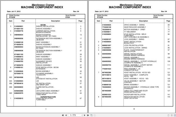
Sheave Installation
Sheave Assembly
Carrier Installation – Boom Extension
Boom Extension Installation – 25″ Fixed
Extension Section Assembly – Jib Boom
Mast Assembly
Boom Extension Assembly – 25’ Fixed
Alignment Device Installation
Stop Installation – Boom Extension
Boom Assembly
Cylinder Assembly – Telescope
Lmi System Kit Installation
Lmi
Kit Installation – 3rd Wrap Limit
Alarm Installation – Lmi
Lmi Alarm Cable Assembly
Indicator Installation – Third Wrap
Drive Installation – Turntable
Drive Assembly – Swing
Gear Reducer Assembly
Motor Assembly – Orbit
T/T Weldment
Stud Installation – Weld Turntable
Lock Assembly – Swing
Shaft Installation – Boom Pivot
Lock Pin Installation
Lock Installation – Swing
Plate, Counterweight Installation
Swivel Installation – Engine Wiring Harness
Swivel Assembly – Engine Wiring Harness
Swivel Assembly – 10 Port Hydraulic (Complete Assembly )
Swivel Assembly – 2 Port Water (Complete Assembly )
Ring Assembly – 43 Conductor Slip
Hoist Installation – Ho15i-16g
Hoist Assembly – Complete Ho15i – 16g
Hoist Assembly – Ho15i – 16g
Valve Assembly – Motor Control
Brake Assembly
Motor Assembly – Hydraulic Vane Type Hydraulic
Cable Follower And Idler Drum Installation
Kicker Bar Installation
Indicator Installation – Hoist Rotation
Resistor Assembly – 6 Ohms
Indicator Installation – Rotation
Harness Assembly – Rotation Sensor
Mirror Installation – Hoist
Cooler Installation – Oil
Cooler Assembly – Oil
Fan Assembly – Electric
Cover Installation – Valve
Hydraulic Lines Installation Test Panel-Superstructure
Hydraulic Lines Installation -Tele (Superstructure)
Hydraulic Lines Installation – Swing
Hydraulic Lines Installation -Lift Superstructure
Bearing Bolt Installation
Hydraulic Lines Installation -Brake (Superstructure)
Lock Pin Switch Installation
Switch Assembly
Hydraulic Lines Installation – Supply, Pressure And Return
Telescope Hydraulic Lines Installation – Superstructure
Lift Hydraulic Lines Installation – Cab
Hydraulic Lines Installation – Throttle
Lower Shaft And Lift Cylinder Installation
Cylinder Assembly – 7.50’’ Lift
Valve Installation – Control
Valve Assembly – Three Section Direction Control
Valve Assembly – Directional Control
Valve Assembly – Lockout Control
Cylinder Assembly – Hydraulic Master
Brake Booster And Master Cylinder Assembly
Cylinder Assembly – Brake Booster And Master
Manifold – 2 Station
Valve Assembly – Residual Check
Valve Installation – Hydraulic
Valve Assembly – Integrated Outrigger/Steer
Valve Assembly – Park Brake (Complete Assembly )
Switch Assembly – Flow
Hydraulic Lines Installation – Main Hoist (Superstructure)
Electrical System Installation – Superstructure
Harness Assembly – Superstructure
Mirror Installation – Turntable
Handles Installation – Control
Work Light Installation
Acoustical Installation
Extinguisher Installation – Fire
Switch Installation – Turn Signal
Mirror Installation – Cab
Cab Installation
Cable Assembly – Control
Console Installation – Front
Console Assembly – Front
Shift Control Assembly
Harness Installation – Front Console
Harness Assembly – Front Console
System Installation – Cab (Superstructure)
Steer Hydraulic Lines Installation – Cab
Lines Installation – Hoist Hydraulic
Frame Section
Stud Installation
Front Axle Installation
Front Axle Assembly
Axle Assembly
Cylinder Assembly – Steer
Hydraulic Lines Installation – Front Steer
Hydraulic Brake Lines
Rear Steer (Carrier)
Indicator Installation – Rear Steer
Tire And Wheel Installation
Tire And Wheel Assembly – Left Hand
Tire And Wheel Assembly – Right Hand
Float Installation – Outrigger
Float Assembly – Outrigger
Hydraulic Lines Installation – Outrigger
Fender Installation
Box Installation – Decking And Storage
Step And Grab Rail Installation
Hydraulic Tank And Step Installation
Tank Assembly – Hydraulic
Filter Assembly – Return
Fuel Tank And Step Installation
Tank Assembly – Fuel
Cover Installation – Battery
Mirror Installation – Rear View
Hook Block Tie-Down Installation
Lights Installation – Exterior
Hood Installation – Engine
Engine Hood Assembly
Weatherstrip Installation
Engine And Transmission Installation –
Engine And Transmission Components Assembly
Engine And Transmission Assembly
Transmission Installation
Transmission Assembly
Transmission Assembly Converter Housing Group
Transmission Assembly Transmission Case And Rear
Transmission Assembly Turbine Shaft Stator Support,
Transmission Assembly Drive Plate Group
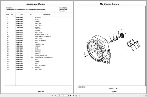
Transmission Assembly Torque Convertor Assembly
Transmission Assembly Auxiliary Pump Parts Group
Transmission Assembly Charging Pump Drive Group
Transmission Assembly Forward Shaft Group
Transmission Assembly Reverse Idler Group
Transmission Assembly Reverse & 2nd Shaft Group
Transmission Assembly Low Speed Shaft Group
Transmission Assembly 3rd Shaft Clutch Group
Transmission Assembly Idler Shaft Group
Transmission Assembly Output Shaft Group
Transmission Assembly Hi & Low Range Shift Group
Transmission Assembly Charging Pump & Filter
Transmission Assembly Valve Mounting Group
Transmission Assembly Valve, Control
Brake Installation – Park
Caliper Assembly – Disc Brake Brake
Chamber Assembly – Spring Applied
Radiator Assembly
Cylinder Assembly – Throttle (Complete Assembly )
Pump Assembly
Electrical System Installation – Engine
Harness Assembly – Engine
Valve Assembly – Solenoid
Cleaner Installation – Air
Cleaner Assembly – Air (Complete Assembly )
Muffler Installation
Cold Start Installation
Driveline Installation
Driveline Assembly – 72n
Driveline Assembly
Coolant Filter Installation
Axle Installation – Rear
Cylinder Assembly – 3″ Lockout
Lines Installation – Axle Lockout Hydraulic
Beam Installation – Outrigger
Beam Assembly – Outrigger
Cylinder Assembly -3 1/2″ Outrigger Jack (Complete Assembly )
Cylinder Assembly – Complete Outrigger Extension
Cylinder Assembly – 2 1/2″ Outrigger Extension
Electrical System Installation – Carrier
Harness Assembly – Carrier
Harness Assy, Outrigger Cab To Board
Panel Assembly – Fuse
Battery Installation With Quick Disconnect
Relay Installation – Outrigger Extension
Decal Installation – Standard
Decal Installation – Rt522b Standard
Decal Installation
Related Products
-
Grove Crane 2024 Collection Parts Document 72.1 GB PDF
Original price was: 1,200.840Current price is: 840. USDThis is an offline spare parts catalog, you need to use this to sell the spare parts and it can help you a little with assembly. It’s from a manufacturer and the best in the world.Hot-30%
REALEASE :
REALEASE :
-
Grove Crane 1.8 Gb YB Series Collection Parts Document PDF
Original price was: 300.70Current price is: 70. USDThis is an offline spare parts catalog, you need to use this to sell the spare parts and it can help you a little with assembly. It’s from a manufacturer and the best in the world.Hot-77%
REALEASE :
REALEASE :
-
Grove Parts Document Crane 7.82 Gb TM TMS TT TTS Series Collection PDF
Original price was: 400.250Current price is: 250. USDThis is an offline spare parts catalog, you need to use this to sell the spare parts and it can help you a little with assembly. It’s from a manufacturer and the best in the world.Hot-38%
REALEASE :
REALEASE :
-
Grove Crane RT GRT Series Collection Parts Document PDF 43 GB
Original price was: 500.340Current price is: 340. USDThis is an offline spare parts catalog, you need to use this to sell the spare parts and it can help you a little with assembly. It’s from a manufacturer and the best in the world.Hot-32%
REALEASE :
REALEASE :
-
Grove RT EPC Spare Parts Catalog Manual 2023 PDF EN
Original price was: 2,000.540Current price is: 540. USDThis is an offline spare parts catalog, you need to use this to sell the spare parts and it can help you a little with assembly. It’s from a manufacturer and the best in the world.Hot-73%
REALEASE :
REALEASE :
-
Grove Parts Document Crane GMK Series Collection 17.1 GB PDF
Original price was: 500.290Current price is: 290. USDThis is an offline spare parts catalog, you need to use this to sell the spare parts and it can help you a little with assembly. It’s from a manufacturer and the best in the world.Hot-42%
REALEASE :
REALEASE :
-
Grove Crane AT ATS Series Collection Parts Document PDF 447 MB
Original price was: 400.70Current price is: 70. USDIf you are a technician, You will need to use this product to repair your vehicleHot-83%
REALEASE :
REALEASE :
-
Grove GMK EPC Spare Part Catalog Manual 2023 PDF EN DE
Original price was: 600.70Current price is: 70. USDThis is an offline spare parts catalog, you need to use this to sell the spare parts and it can help you a little with assembly. It’s from a manufacturer and the best in the world.Hot-88%
REALEASE :
REALEASE :