
2 ITEMSVIEW CART


Total: 120.00

Expert Support
Full Speed
100% Working
20 USD
Contents:
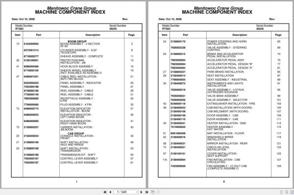
Boom Assembly – 3 Section 25’-60’
Cylinder Assembly – 6.50’’ Telescope
Sheave Assembly – Complete
Protection Bar Installation – Jib
Hook Block Assembly
Sheave Wheel Assembly (Not Available As Assembly )
Cable Reel Installation – Anti-Two Block
Panel Assembly – Indicator
Panel Assembly
Reel Assembly – Cable
Receptacle Assembly – 6 Pin
Plug Assembly – 6 Pin
Elevation Indicator Installation – Boom
Elevation Indicator – Left Hand Boom
Elevation Indicator – Right Hand Boom
Carrier Installation – Jib Boom
Console Installation – Front
Shift Installation – Axle And Range
Shift Installation – Transmission
Transmission Kit – Shift
Control Lever Assembly
Power Steering And Horn Installation
Valve Assembly – Steering Control
Brake And Accelerator Pedal Installation
Accelerator Pedal Assy
Accelerator Pedal Design “B”
Accelerator Pedal Design “A”
Park Brake Installation
Seat Installation
Seat Assembly – Industrial
Instruments And Lights Installation
Valve Assembly – 4 Stack Outrigger Solenoid
Valve Bank Assembly
Valve Assembly – Selector
Extinguisher Installation – Fire
Cab Installation (With Doors)
Cab Weldment (With Doors)
Door Assembly – Cab
Heater Installation – Gmc
Heater Assembly – Hot Water
Mat Installation – Floor
Windshield Wiper Installation
Mirror Installation – Rear
Circular Level Installation
Cover Installation – Seat Support
Fan Installation – Cab Circulating
Fan Assembly – 12 Volt Cab (Complete Assembly )
Control Valve And Linkage Installation
Valve Bank Assembly – 2 Section (A-20 Series)
Valve Assembly – Section Outlet (A-20 Series)
Valve Assembly – Section Inlet (A-20 Series)
Valve Assembly – 4 Section
Valve Assembly – Outlet
Valve Section – Inlet (A-35 Series)
Cartridge Assembly
Valve Assembly – Relief 1000 Psi
Valve Bank Assembly – 1 Section
Valve Assembly – Relief 2250 Psi
Hydraulic Lines Installation – Swing
Valve Assembly – Relief
Hydraulic Lines Installation – Lift
Hydraulic Lines Installation – Mid-Telescope
Hydraulic Lines Installation – Main Hoist
Hose Clamps Installation – Main Hoist
Hoist Installation – Main And/Or Auxiliary
Hoist Assembly – Model Ho15b-11
Gear Reduction Assembly
Motor Assembly – Hydraulic
Idler Drum Assembly
Turntable Drive Installation
Swing Box And Brake Assembly
Brake Assembly – Swing
Motor Assembly – Orbit
Counterweight Installation
Cylinder Installation – Lift
Cylinder Assembly – Lift
Swivel Installation – Electric/Hydraulic
Swivel Coupling Assembly – Electric
Swivel Assembly – 7 Port Hydraulic
Turntable Lock Installation
Pivot Shaft Installation – Boom
Engine Installation – Gmc 4-53n
Radiator Installation (Not Available As Assembly )
Exhaust And Air Cleaner Installation
Cleaner Assembly – Air
Filter Assembly – Oil
Pump Assembly – Steering
3 Stage Pump Installation
Pump Assembly
Hood Installation – Engine
Transmission Installation
Transmission Assembly
Transmission Assembly Front Cover And Case Assembly
Transmission Assembly Clutch And Gear Group
Transmission Assembly Axle Disconnect Assembly
Transmission Assembly Low Clutch Assembly
Transmission Assembly Forward Clutch Assembly
Transmission Assembly Third Clutch Assembly
Transmission Assembly Reverse And Second Shift
Transmission Assembly Control Valve Assembly
Bottom Cable Entry Kit
Driveline Installation
Driveline Assembly
Transmission/Converter Lines Installation
Axle Installation – Front
Axle Assembly
Axle Assembly Differential Carrier Assembly
Axle Assembly Housing Assembly
Axle Assembly Hub And Shaft Group
Axle Assembly Brake Assembly
Axle Assembly Wheel Cylinder Assembly
Cylinder Assembly – Steer (Complete Assembly )
Axle Installation – Rear
Tire And Wheel Assembly
Power Boost And Brake Lines Installation
Cylinder Assembly – Master With Power Head
Power Brake Assembly
Cylinder Assembly – Master
Valve Assembly – Flow Control
Axle Oscillation Lockout Installation
Cylinder Assembly -Lockout
Indicator Installation – Rear Steer
Switch Assembly – Limit
Light Installation – Red Indicator
Hydraulic Lines Installation – Front Steer
Hydraulic Lines Installation – Rear Steer
Hydraulic Lines Installation – Axle Lockout
Lug Nut And Washer Installation
Outrigger Installation
Cylinder Assembly – 7″ Outrigger Jack
Valve Installation – Selector
Valve Assembly – Outrigger Selector
Reservoir Installation – Hydraulic
Tank Installation – Fuel
Electrical Systems Installation – Carrier
Tool Box Step And Handle Installation – W/O Fenders
Cover Installation – Front
Battery Installation
Pintle Hook Installation
Pintle Hook
Alarm Installation – Back-Up
Tie Down Installation – Hook Block
Decal Installation – Rt58b,Rt58c,Rt58d
Hydraulic Lines Installation – Supply, Pressure And Return
Hydraulic Lines Installation – Outrigger

REALEASE :
REALEASE :

REALEASE :
REALEASE :

REALEASE :
REALEASE :

REALEASE :
REALEASE :

REALEASE :
REALEASE :

REALEASE :
REALEASE :

REALEASE :
REALEASE :

REALEASE :
REALEASE :
 Automotive - Heavy Equipment - Truck & Bus - Forklift - Crane