
0 ITEMSVIEW CART


✓
Expert Support
✓
Full Speed
✓
100% Working
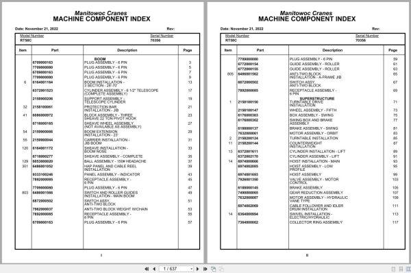
Grove Crane RT58C 70356 Parts Manual 2022
Size: 4.05 MB
Format: PDF
Language: English
Brand: Grove
Type of Machine: Crane
Type of Manual: Parts Manual
Model: Grove RT58C Crane
Serial Number: 70356
Publication Date: 2022
Number of Pages: 637 Pages
40 USD
- Description
Description
Contents:
Plug Assembly – 6 Pin
Boom Installation -3 Section – 28′-70′
Cylinder Assembly – 6 1/2″ Telescope(Complete Assembly )
Support Assembly -Telescope Cylinder
Protection Bar Installation – Jib
Block Assembly – Three Sheave 22 Ton Pivot Hook
Sheave Wheel Assembly (Not Available As Assembly )
Boom Extension Installation – 23′
Carrier Installation -Jib Boom
Sheave Installation -Boom Nose
Sheave Assembly – Complete
Ball Assembly – 150# Headache
Hap Panel And Cable Reel Installation
Panel Assembly – Indicator
Receptacle Assembly -6 Pin
Switch And Roller Guides Installation – Main Boom
Switch Assy,Anti-Two Block
Anti-Two Block Weight W/Chain
Guide Assembly – Roller
Anti-Two Block Installation – A-Frame Jib
Turntable Drive Installation
Wheel Assembly – Fifth
Box Assembly – Swing
Swing Box And Brake Assembly
Brake Assembly – Swing
Motor Assembly – Orbit
Turntable Installation
Counterweight Installation
Cylinder Installation – Lift
Cylinder Assembly – Lift
Hoist Installation – Main
Hoist Assembly – Low Profile
Hoist Assembly
Valve Assembly – Motor control
Brake Assembly
Gear Reduction Assembly
Motor Assembly – Hydraulic Vane Type
Cable Follower And Idler Drum Installation
Swivel Installation -Electric/Hydraulic
Collector Ring Assembly
Swivel Assembly – 7 Port Hydraulic
Control Valve And linkage Installation
Valve Bank Assembly -2 Section (A-20 Series)
Valve Assembly – Section inlet (A-20 Series)
Valve Assembly -4 Section
Valve Assembly – Outlet
Valve Section – Inlet(A-35 Series)
Cartridge Assembly
Valve Assembly – Relief1000 Psi
Valve Bank Assembly -1 Section
Valve Assembly – Relief2250 Psi
Valve Assembly – Solenoid
Cylinder Assembly -Lockout
Valve Assembly -Flow Divider
Turntable Lock Installation
Rotation Indicator Installation
Driver Assembly driver Assembly
Indicator Assembly
Transmitter Assembly
Hydraulic Lines Installation -Swing
Hydraulic Lines Installation – Lift
Hydraulic Lines Installation -Mid-Telescope
Hydraulic Lines Installation -Main Hoist
Hydraulic Lines Installation -Lever Lockout
Hose Clamps Installation – Main Hoist
Idler Drum And Cable Follower Installation
Cable Follower
Idler Drum Assembly
Pivot Shaft Installation -Boom
Console Installation -Front
Shift Installation -Axle And Range
Shift Installation -Transmission
Transmission Kit – Shift
Control Lever Assembly
Power Steering And Horn Installation
Valve Assembly – Steering control
Park Brake Installation
Seat And Seat Belt Installation
Seat Assembly – Industrial
Electrical Systems Installation – S/S
Instruments And Lights Installation
Extinguisher Installation – Fire
Cab Installation (With Doors)
Cab Weldment (With Doors)
Door Assembly – Cab
Windshield Wiper Installation
Windshield Washer Installation
Mirror Installation – Rear
Circular Level Installation
Cover Installation -Seat Support
Fan Installation – Cab circulating
Fan Assembly – 12 Volt Cab(Complete Assembly )
Alarm Installation -Audio/Visual
Handrail Installation
Mounting Chart Installation – Load Chart
Heater Installation -Propane
Heater Assembly – Propane
Cover Plate Installation -Heater
Axle Installation – Front
Axle Assembly
Axle Assembly differential Carrier Parts
Axle Assembly housing Parts
Axle Assembly wheel End Parts
Axle Assembly Brake Parts
Axle Assembly wheel Cylinder Assembly
Cylinder Assembly – 3″Steer
Axle Installation – Rear
Cylinder Assembly -Lockout
Outrigger Installation
Cylinder Assembly -7″ Outrigger Jack
Transmission Installation
Transmission Assembly
Transmission Assembly front Cover And Case Assembly
Transmission Assembly clutch And Gear Group
Transmission Assembly axle Disconnect Assembly
Transmission Assembly low Clutch Assembly
Transmission Assembly forward Clutch Assembly
Transmission Assembly third Clutch Assembly
Transmission Assembly reverse And Second Shift
Transmission Assembly control Valve Assembly
Bottom Cable Entry Kit
Engine Installation -Deutz F6l912
Filter Assembly – Oil
Pump Assembly -(W/O Return To Center Steering )
Hood Installation – Engine
Door Assembly – Right Hand
Door Assembly – Left Hand Side
Driveline Installation
Driveline Assembly
Reservoir Installation -Hydraulic
Tire And Wheel Assembly
Tank Installation – Fuel
Transmission/Converter Lines Installation
Power Boost And Brake lines Installation
Cylinder Assembly -Master With Power Head
Power Brake Assembly
Cylinder Assembly – Brake master
Valve Assembly -Flow Control
Valve Assembly – Relief
Valve Installation -Rear Axle Lockout
Valve Assembly
Electrical Systems Installation – Carrier
Harness Assembly – Carrier
Harness Assembly – Deutz Enginef6l912 Engine
Tool Box Step And Handle Installation – W/Fenders
Cover Installation – Front
Battery Installation
Lights Installation -Front And Rear
Fender Installation
Indicator Installation -Rear Steer
Switch Assembly – Limit
Pintle Hook Installation
Pintle Hook
Alarm Installation -Back-Up
Quick Start Installation
Hydraulic Lines Installation -Supply, Pressure And Return
Hydraulic Lines Installation -Outrigger
Hydraulic Lines Installation -Front Steer
Hydraulic Lines Installation -Rear Steer
Hydraulic Lines Installation -Axle Lockout With Override
Valve Installation -Selector
Valve Assembly – Outrigger selector
Heater Installation -Engine Oil Pan
Lug Nut And Washer Installation
Belt & Filter Deutz F6l 912
Wiring Diagram – Krueger
Related Products
-
Grove Crane RT GRT Series Collection Parts Document PDF 43 GB
Original price was: 500.340Current price is: 340. USDThis is an offline spare parts catalog, you need to use this to sell the spare parts and it can help you a little with assembly. It’s from a manufacturer and the best in the world.Hot-32%
REALEASE :
REALEASE :
-
Grove Crane 2024 Collection Parts Document 72.1 GB PDF
Original price was: 1,200.840Current price is: 840. USDThis is an offline spare parts catalog, you need to use this to sell the spare parts and it can help you a little with assembly. It’s from a manufacturer and the best in the world.Hot-30%
REALEASE :
REALEASE :
-
Grove Crane AT ATS Series Collection Parts Document PDF 447 MB
Original price was: 400.70Current price is: 70. USDIf you are a technician, You will need to use this product to repair your vehicleHot-83%
REALEASE :
REALEASE :
-
Grove Parts Document Crane 7.82 Gb TM TMS TT TTS Series Collection PDF
Original price was: 400.250Current price is: 250. USDThis is an offline spare parts catalog, you need to use this to sell the spare parts and it can help you a little with assembly. It’s from a manufacturer and the best in the world.Hot-38%
REALEASE :
REALEASE :
-
Grove Parts Document Crane GMK Series Collection 17.1 GB PDF
Original price was: 500.290Current price is: 290. USDThis is an offline spare parts catalog, you need to use this to sell the spare parts and it can help you a little with assembly. It’s from a manufacturer and the best in the world.Hot-42%
REALEASE :
REALEASE :
-
Grove RT EPC Spare Parts Catalog Manual 2023 PDF EN
Original price was: 2,000.540Current price is: 540. USDThis is an offline spare parts catalog, you need to use this to sell the spare parts and it can help you a little with assembly. It’s from a manufacturer and the best in the world.Hot-73%
REALEASE :
REALEASE :
-
Grove Crane 1.8 Gb YB Series Collection Parts Document PDF
Original price was: 300.70Current price is: 70. USDThis is an offline spare parts catalog, you need to use this to sell the spare parts and it can help you a little with assembly. It’s from a manufacturer and the best in the world.Hot-77%
REALEASE :
REALEASE :
-
Grove GMK EPC Spare Part Catalog Manual 2023 PDF EN DE
Original price was: 600.70Current price is: 70. USDThis is an offline spare parts catalog, you need to use this to sell the spare parts and it can help you a little with assembly. It’s from a manufacturer and the best in the world.Hot-88%
REALEASE :
REALEASE :