
8 ITEMSVIEW CART


Total: 395.00
Expert Support
Full Speed
100% Working
20 USD
Contents:
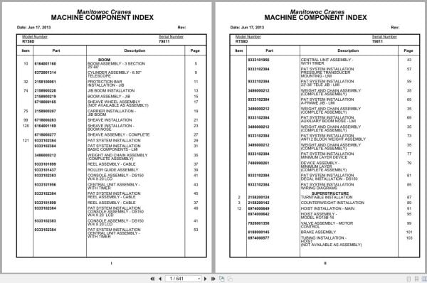
Boom Assembly – 3 Section 25′-60′
Cylinder Assembly – 6.50” Telescope
Protection Bar Installation – Jib
Jib Boom Installation
Boom Assembly – Jib
Sheave Wheel Assembly (Not Available As Assembly )
Carrier Installation – Jib Boom
Sheave Installation
Sheave Installation – Boom Nose
Sheave Assembly – Complete
Pat System Installation
Pat System Installation Basic Components – Lmi
Weight And Chain Assembly (Complete Assembly )
Reel Assembly – Cable
Roller Guide Assembly
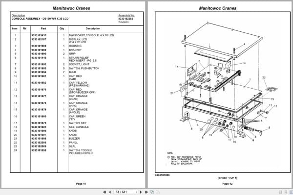
Console Assembly – Ds150 W/4 X 20 Lcd
Central Unit Assembly – With Timer
Pat System Installation Reel Assembly – Cable
Pat System Installation Console Assembly – Ds150
Pat System Installation Central Unit Assembly –
Pat System Installation Pressure Transducer
Pat System Installation 23′-38′ Tele Jib – Lmi
Pat System Installation A-Frame Jib – Lmi
Pat System Installation Auxiliary Boom Nose – Lmi
Pat System Installation Anti 2 Block Weight Assembly
Pat System Installation Minimum Layer Device
Device Assembly – Minimum Layer
Pat System Installation Decal Installation – Ds150
Pat System Installation Wiring Diagrams
Turntable Installation
Counterweight Installation
Hoist Installation – Main
Hoist Assembly – Model Ho15b-16
Valve Assembly – Motor Control
Brake Assembly
Tubing Installation – Hoist
Gear Reduction Assembly
Motor Assembly – Hydraulic Vane Type
Cylinder Installation – 9.00” Lift
Cylinder Assembly – Lift
Swivel Installation – Electric Hydraulic
Swivel Assembly – Electric And Hydraulic
Swivel Assembly – Hydraulic 7 Port
Swivel Assembly
Swivel Assembly – 7 Port Hydraulic
Electric Swivel Installation
Ring Assembly – Slip
Control Valve And Linkage Installation
Valve Assembly – 2 Section Control
Bank Assembly – 4 Section Control Valve
Valve Assembly – Outlet
Valve Assembly – 1 Section Control
Valve Assembly – Solenoid
Valve Assembly – Flow Divider
Turntable Lock Installation
Indicator Installation – Main Hoist Rotation
Hydraulic Lines Installation – Swing
Hydraulic Lines Installation – Lift
Hydraulic Lines Installation – Mid-Telescope
Hydraulic Lines Installation – Main Hoist
Hydraulic Lines Installation – Lever Lockout
Hose Clamps Installation – Main Hoist
Pivot Shaft Installation – Boom
Turntable Drive And Swing Box Installation
Box Assembly – Swing
Swing Box And Brake Assembly
Brake Assembly – Swing
Motor Assembly – Orbit
Test Panel Installation – Hydraulic
Console Installation – Front
Shift Installation – Axle And Range
Shift Installation – Transmission
Transmission Kit – Shift
Control Lever Assembly
Power Steering And Horn Installation
Valve Assembly – Steering Control
Brake And Accelerator Pedal Installation
Accelerator Pedal Assy
Accelerator Pedal Design “B”
Accelerator Pedal Design “A”
Park Brake Installation
Seat Installation
Seat Assembly – Cloth
Electrical System Installation
Instruments And Lights Installation
Light Installation – Red Indicator
Extinguisher Installation – Fire
Cab Installation (With Doors)
Cab Weldment (With Doors)
Door Assembly – Cab
Heater Installation
Heater Assembly – Hot Water
Fan Installation – Cab Circulating
Fan Assembly – 12 Volt Cab (Complete Assembly )
Mat Installation – Floor
Windshield Wiper Installation
Windshield Washer Installation
Mirror Installation – Rear
Circular Level Installation
Cover Installation – Seat Support
Handrail Installation
Hydraulic Lines Installation – Test Panel
Fifth Wheel Installation
Axle Installation – Front
Axle Assembly
Axle Assembly Differential Carrier Parts
Axle Assembly Housing Parts
Axle Assembly Wheel End Parts
Axle Assembly Brake Parts
Axle Assembly Wheel Cylinder Assembly
Cylinder Assembly – 3″ Steer
Axle Installation – Rear
Cylinder Assembly – 5″ Lockout
Axle Assembly Differential Carrier Assembly
Axle Assembly Housing Assembly
Axle Assembly Hub And Shaft Group
Axle Assembly Brake Assembly
Outrigger Installation
Cylinder Assembly – 7″ Outrigger Jack
Transmission Installation
Transmission Assembly
Transmission Assembly Case And Cover Group
Transmission Assembly Idler Shaft And Front Cover
Transmission Assembly Forward Shaft Group
Transmission Assembly Reverse Idler Group
Transmission Assembly Reverse And Second Shaft
Transmission Assembly Low Speed Shaft Group
Transmission Assembly Third Shaft Clutch Group
Transmission Assembly Idler Shaft Group
Transmission Assembly Output Shaft Group
Transmission Assembly Hi And Low Range Shift
Transmission Assembly Control Valve
Bottom Cable Entry Kit
Engine Installation – Cummins 6bt5.9
Filter Assembly – Oil
Pump Assembly – (W/O Return To Center Steering )
Hood Installation – Engine
Door Assembly – Right Hand
Door Assembly – Left Hand Side
Pump Cover Installation
Driveline Installation
Driveline Assembly
Reservoir Installation – Hydraulic
Tank Installation – Fuel
Hydraulic Lines Converter And Transmission
Power Boost And Brake Lines Installation
Cylinder Assembly – Master With Power Head
Power Brake Assembly
Cylinder Assembly – Brake Master
Valve Assembly – Flow Control
Valve Assembly – Relief
Valve Installation – Rear Axle Lockout
Valve Assembly – Rear Axle Lockout
Electrical System Installation – Carrier
Harness Assembly – Carrier
Step And Grab Handle Installation
Cover Installation – Front
Battery Installation – Cummins 6bt5.9
Lights Installation – Front And Rear
Fender Installation
Indicator Installation – Rear Steer
Switch Assembly – Limit
Alarm Installation – Back-Up
Hydraulic Lines Installation – Supply, Pressure And Return
Hydraulic Lines Installation – Outrigger
Hydraulic Lines Installation – Front Steer
Hydraulic Lines Installation – Rear Steer
Hydraulic Schematic – Axle Lockout
Indicator Installation – Air Restriction
Lug Nut And Washer Installation
Valve Installation – Selector
Valve Assembly – Outrigger Selector
Decal Installation – Rt58b

REALEASE :
REALEASE :

REALEASE :
REALEASE :

REALEASE :
REALEASE :

REALEASE :
REALEASE :

REALEASE :
REALEASE :

REALEASE :
REALEASE :

REALEASE :
REALEASE :

REALEASE :
REALEASE :
 Automotive - Heavy Equipment - Truck & Bus - Forklift - Crane