
8 ITEMSVIEW CART


Total: 450.00

Expert Support
Full Speed
100% Working
40 USD
Contents:
Plug Assembly – 6 Pin
Switch And Roller Guides Installation – Main Boom
Switch Assy,Anti-Two Block
Anti-Two Block Weight W/Chain
Guide Assembly – Roller
Receptacle Assembly -6 Pin
A2b Installation -Rooster Sheave
Anti-Two Block Installation – Swing Away
Boom Assembly – 3 Section32′-80′
Cylinder Assembly -Telescope
Sheave Assembly – Complete
Nose Assembly – Boom Extension
Carrier Installation -Boom Extension
Rooster Sheave Installation
Sheave Wheel Assembly (Not Available As Assembly)
Boom Extension Installation
Roller Assembly – Cable
Sheave Wheel Assembly
Alignment Device – Boom Extension
Hook Block Assembly
Sheave Installation -Boom Nose
Panel And Reel Installation -Krueger Hlap
Panel Assembly – Indicator
Receptacle Assembly -10 Pin
Plug Assembly – 10 Pin
Ball Assembly – 150# Headache
Pintle Hook Installation
Pintle Hook Assembly
Turntable Drive Installation
Swing Box Assembly -Complete
Swing Box And Brake Assembly
Brake Assembly – Swing
Motor Assembly – Orbit
Pivot Shaft Installation -Boom
Swivel Installation -Electric/Hydraulic
Swivel Assembly -Hydraulic
Swivel Assembly -Air/Hydraulic
Ring Assembly – Slip36 Conductor
Control Valve And Linkage Installation
Valve Bank Assembly -1 Section
Valve Assembly – Outlet
Valve Section – Inlet(A-35 Series)
Valve Assembly – Relief2250 Psi
Cartridge Assembly
Valve Bank Assembly -2 Section (A-20 Series)
Valve Assembly – Section Inlet (A-20 Series)
Valve Bank Assembly -4 Section (A-35 Series)
Cartridge Assembly -Relief Valve
Valve Assembly – Relief1000 Psi
Cylinder Assembly -Lockout
Cylinder Installation -Lift
Cylinder Assembly – Lift
Hoist Installation – Main Or Auxiliary
Hoist Assembly – High Profile
Hoist Assembly
Valve Assembly – Motor Control
Brake Assembly
Gear Reduction Assembly
Motor Assembly – Hydraulic Vane Type
Counterweight Installation
Warning Device Installation
Rotation Indicator Installation
Driver Assembly driver Assembly
Indicator Assembly
Transmitter Assembly
Hydraulic Lines Installation -Free Swing W/Lever Lockout
Hydraulic Lines Installation – Lift
Hydraulic Lines Installation -Mid – Telescope
Hydraulic Lines Installation -Main And Auxiliary
Valve Installation -Reducing/Relief (Swing)
Valve Assembly -Pressure And Sequence
Bearing Bolt Installation
Valve Installation – Lever Lockout Solenoid
Valve Assembly – Solenoid
Lock Pin Installation -Turntable
Panel Installation -Hydraulic Test
Hydraulic Lines Installation -Lever Lockout
Cooler Installation – Oil
Fan Assembly – Electric
Idler Drum Installation -Hoist
Cable, Hoist
Cab Installation
Cab Assembly
Latch Kit – Door
Valve Assembly – Transmission Shift Control
Pedal And Valve Assembly -Accelerator
Valve Assembly – Control
Valve Assembly – Dual Brake
Valve Assembly -Selector
Fan Installation – Cab Circulating
Fan Assembly – 12 Volt Cab(Complete Assembly)
Extinguisher Installation – Fire
Heater And Defroster Installation
Heater Assembly – Diesel
Heater Assembly – Diesel Exhaust Parts
Heater Assembly – Diesel Case And Heater Exchanger
Heater Assembly – Diesel Parts
Heater Assembly – Diesel Fuel And Ignition Systems
Heater Assembly – Diesel Control Panel Parts
Heater Assembly – Diesel Circuit Board Parts
Heater Assembly – Diesel Carburetor Parts
Heater Assembly – Diesel Motor And Blower Parts
Heater Assembly – Diesel Remote Control Parts
Seat Assembly
Valve Installation – Steer Control
Control Assembly -(W/O Return To Center Steering)
Valve Assembly -Spring Brake
Weatherstrip Installation – Cab
Spotlight Installation
Spotlight
Valve And Pedal Installation – Swing Brake
Valve Assembly -Power Brake
Electrical System Installation – S/S
Wiring Harness Assembly -Superstructure
Panel Assembly – Fuse And Connector
Harness Assembly -Fuse And Connector Panel
Acoustical Installation
Wiper And Washer Installation – Windshield
Air Lines Installation -Superstructure
Seat Installation
Warning System Installation
Grab Rail Installation
Instruments And Lights Installation
Cab Supplement -Work Lights
Frame – 5th Wheel
Axle Installation – Front
Axle Assembly
Axle Assembly differential Carrier Assembly
Axle Assembly housing Assembly
Axle Assembly hub And Shaft Group
Axle Assembly brake Assembly
Axle Assembly air Brake Chamber
Cylinder Assembly – Steer(Complete Assembly)
Axle Installation – Rear
Cylinder Assembly – 3″Steer
Transmission Installation
Transmission Assembly
Transmission Assembly case And Cover Group
Transmission Assembly input Shaft And Front Cover
Transmission Assembly forward Shaft Group
Transmission Assembly reverse Idler Group
Transmission Assembly reverse And Second Shaft
Transmission Assembly low Speed Shaft Group
Transmission Assembly third Shaft Clutch Group
Transmission Assembly idler Shaft Group
Transmission Assembly output Shaft Group
Transmission Assembly hi And Low Range Shift
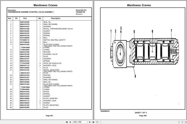
Transmission Assembly control Valve Assembly
Valve Assembly transmission
Engine Installation -Cummins 6bt5.9
Filter Assembly – Oil
Pump Assembly – Steer
Cylinder Assembly – Throttle
Driveline Installation
Driveline Assembly
Reservoir Installation -Hydraulic
Air Tank And Valve Installation
Valve, Relay
Valve Installation -Outrigger
Valve Assembly – Outrigger Selector(Complete Assembly)
Valve Assembly – 4 Stack Outrigger Solenoid
Valve Assembly – Sequence
Tire And Wheel Assembly
Tool Box Installation
Pad And Storage Installation – Outrigger
Float Assembly – Outrigger
Suction Line And Manifold Installation
Valve Installation -Rear Axle Lockout
Valve Assembly – Lockout
Valve Installation – Front Steer Relief
Valve Assembly – Relief(See Separate Parts List)
Hydraulic Shift-Converter Line Installation
Mirror Installation -Rear View
Lights And Turn Signals Installation
Fenders Installation
Indicator Installation -Rear Steer
Switch Assembly – Limit
Hydraulic Lines Installation -Outrigger
Hydraulic Schematic -Front Steer
Hydraulic Lines Installation -Rear Steer
Hydraulic Lines Installation -Axle Lockout
Hood Installation – Engine
Air Lines Installation -Brake And Throttle
Dryer Assembly – Air
Ladders Installation -Rear
Electrical System Installation – Carrier
Harness Assembly -Carrier Frame
Alarm Installation -Back-Up
Battery Box Installation
Lug Nut And Washer Installation
Belt & Filter Cummins 6bt5.9
Battery Installation
Outrigger Beam Installation
Cylinder Assembly -Stabilizer
Cylinder Assembly -Extension
Fuel Tank Installation
Guard Installation – Fan
Hydraulic Lines Installation -Supply, Pressure And Return
Valve Assembly – Check
Hasp And Staple Installation
Tie Down Installation -Hook Block
Supplementary Electrical System Installation
Wiring Diagram – Krueger
Decal Installation -Rt600 Series

REALEASE :
REALEASE :

REALEASE :
REALEASE :

REALEASE :
REALEASE :

REALEASE :
REALEASE :

REALEASE :
REALEASE :

REALEASE :
REALEASE :

REALEASE :
REALEASE :

REALEASE :
REALEASE :
 Automotive - Heavy Equipment - Truck & Bus - Forklift - Crane