
3 ITEMSVIEW CART


Total: 110.00
Expert Support
Full Speed
100% Working
30 USD
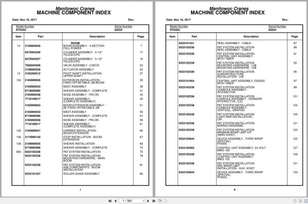
Contents:
Boom Assembly – 4 Section Full Power
Cylinder Assembly – 5 1/2″ Telescope
Valve Assembly – Check
Actuator Assembly
Pivot Shaft Installation – Upper Shaft
Extension Installation – Fixed Offset Table Jib Boom
Mast Assembly
Sheave Assembly – Complete
Nose Assembly – Pin On
Sheave Assembly (Complete Assembly)
Boom Extension Assembly – 29′ Fixed Offset Table Jib
Carrier Installation – Boom Extension
Stop Installation – Boom Extension
Sheave Installation
Pat System Installation
Pat System Installation Mounting Hardware – Main
Pat System Installation A2b Components – Boom
Roller Guide Assembly
Reel Assembly – Cable
Pat System Installation Reel Assembly – Cable
Pat System Installation Central Unit Assembly –
Pat System Installation Mounting Hardware – Lmi
Pat System Installation Superstructure
Central Unit Assembly , Ds350g With Timer
Pat System Installation Console Assembly –
Pat System Installation Console Assembly – Ds350gw
Pat System Installation Light Bar Installation –
Pat System Installation Wiring Diagrams
Pat System Installation Minimum Wrap Limit Kit
Device Assembly , Third Wrap (Special)
Control Unit Assembly , 24 Volt Mwd 100
Pat System Installation Control Unit Assembly –
Pat System Installation 3rd Wrap Limit
Pat System Installation 3rd Wrap Device – Special
Pat System Installation Auxiliary Boom Nose
Pat System Installation Extension Installation
Pat System Installation Tele-Extension
Pat System Installation Boom Extension Base Kit
Pat System Installation Pin On Stub Nose / Boom
Pat System Installation Jumper Cable Assembly
Pat System Installation Weight Assembly – A2b
Pat System Installation Decal – Lmi
Turntable Drive Installation
Box Assembly – Swing Complete
Swing Box And Brake Assembly
Brake Assembly – Swing (Complete Assembly)
Motor Assembly – Orbit
Lock Assembly – Swing
Plate, Counterweight Installation
Lower Shaft And Lift Cylinder Installation
Cylinder Assembly – 10.00” Lift
Hoist Installation – Main
Hoist Assembly
Motor Assembly – Hydraulic Vane Type (Complete Assembly)
Brake Assembly
Cable Follower And Idler Drum Assembly
Indicator Installation – Hoist Rotation
Rotation Indicator Assembly
Bearing Bolt Installation
Positive Swing Lock Installation
Lever Installation
Electrical System Installation – S/S
Harness Assembly – Superstructure
Kicker Bar Installation
Kicker Bar Assembly
Swivel Installation – Electric And Hydraulic
Swivel Assembly – Electric And Hydraulic
Swivel Assembly – 15 Port Hydraulic
Slip Ring Assembly – 44 Conductor
Valve Installation – Control Main And Auxiliary Hoist
Valve Assembly – 2 Section Control
Valve Assembly – 2 Section
Valve Assembly – 1 Section Control
Cylinder Assembly – Brake Booster Master
Cylinder Assembly – Master And Brake Booster
Valve Assembly – Pressure Reducing
Valve Assembly – Flow Control
Valve Assembly – Sequence
Valve Assembly – 5 Station Solenoid
Hydraulic Lines Installation – Supply, Pressure And Return
Valve Assembly – Residual Check
Hydraulic Lines Installation – Brake
Hydraulic Lines Installation – Telescope
Hydraulic Lines Installation – Swing
Hydraulic Lines Installation – Swing And Swing Brake
Hydraulic Lines Installation – Main And Auxiliary Hoist
Hydraulic Lines Installation – Main Hoist
Hydraulic Lines Installation – Lift
Hydraulic Lines Installation – Hydraulic Heater
Hydraulic Lines Installation – Pressure Check Panel
Mirror Installation – Hoist
Flow Divider Installation
Valve Assembly – Flow Divider
Sensor Installation – Swing Lock Pin Position
Switch Assembly
Lube Installation – Turntable Manual Bearing
Pin Installation – Turntable Lock Installation
Cab Installation – Superstructure
Cab Assembly
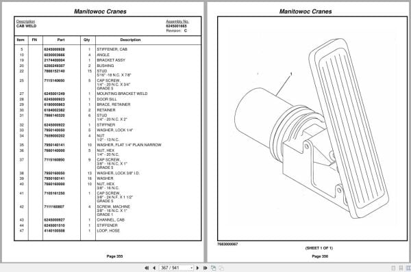
Cab Weld
Valve Assembly – Treadle
Cable Assembly – Control
Motor Assembly – Wiper (Complete Assembly)
Door Assembly
Skylight Assembly – Sliding
Column Assembly – Steering (Complete Assembly)
Valve Assembly – Orbital (W/O Return To Center Steering)
Extinguisher Installation – Fire
Electrical System Installation – Cab
Harness Assembly – Cab
Panel Assembly – Circuit Breakers
Harness Assembly – Circuit Breaker
Console Installation – Front
Console Assembly – Front
Control Assembly – Shift
Gauge Cluster – 12v
Harness Installation – Front Console
Harness Assembly – Console
Control Handles Installation
Pedal Installation – Swing Brake
Screen Installation – Sun Open Mesh
Heater Installation – Hydraulic
Heater Assembly
Heater Panel Installation
Harness Assembly – Heater Panel
Valve Installation – Hydraulic Heater
Valve Assembly – Solenoid
Valve Assembly – Relief 2500 Psi
Heater Valve Installation
Seat Installation – Control Single Axis With Auxiliary
Control Seat Assembly – Single Axis
Seat Assembly
Plate Assembly
Controller Assembly – Single Axis
Harness Assembly – Seat Arm
Harness Assembly – Seat
Suspension Assembly – Seat
Fan Installation – Cab Circulating
Fan Assembly – 12 Volt Cab (Complete Assembly)
Floor Mat Installation – Gray
Pedal Installation – Boom Telescope
Rocker Pedal – Single Function
Washer Installation – Windshield
Hydraulic Lines Installation – Heater
Acoustical Installation
Wiper/Washer Installation – Skylight
Work Light Installation
Covers Installation – Bottom
Frame Section
Stud Installation
Axle Installation – Front
Chamber Assembly – Brake
Axle Assembly – Drive/Steer
Axle Assembly – Drive/Steer Differential Carrier Assembly
Axle Assembly – Drive/Steer Housing Assembly
Axle Assembly – Drive/Steer Wheel End Parts
Axle Assembly – Drive/Steer Caliper Assembly
Cylinder Assembly – 3″ Steer
Axle Installation – Rear
Axle Assembly – Rear
Axle Assembly – Drive/Steer Carrier Assembly
Cylinder Assembly – 5″ Lockout
Beam Installation – Outrigger
Cylinder Assembly – 4 1/2″ Outrigger Jack
Cylinder Assembly – 2 1/2″ Outrigger Extension
Beam Assembly – Outrigger
Driveline Installation
Driveline Assembly
Shaft Assembly – Drive
Mirror Installation – Frame
Relief Valve And Parking Brake Installation
Valve Assembly – Relief
Valve Assembly – Park Brake (Complete Assembly)
Exterior Lights Installation – Carrier
Battery Installation
Cover Installation – Battery
Electrical System Installation – Carrier
Harness Assembly – Carrier
Box Assembly – Relay
Harness Assembly – Relay Box
Rear Steer Indicator Installation
Fender Installation
Hydraulic Reservoir Installation
Reservoir Assembly – Hydraulic
Cover Assembly – 16 1/4″ Inspection Inspection
Filter Assembly – Return
Fuel Tank And Step Installation
Radiator Installation
Cooler Installation – Oil
Fan Assembly
Decking Installation
Outrigger Control Valve Installation
Valve Assembly – 4 Stack Outrigger Solenoid
Valve Assembly
Tie Down Installation – Hook Block
Outrigger Float Stowage Installation
Float Assembly – Outrigger
Back-Up Alarm Installation
Valve Installation – Rear Axle Lockout
Weatherstrip Installation
Supply, Pressure And Return Hydraulic Lines Installation –
Hydraulic Lines Installation – Outrigger
Hydraulic Lines Installation – Front Steer
Hydraulic Lines Installation – Rear Axle Lockout
Hydraulic Lines Installation – Rear Steer
Hydraulic Heater Lines
Hydraulic Lines Installation – Steer
Cleaner Installation – Air
Cleaner Assembly – Air (Complete Assembly)
Exhaust System Installation
Tire And Wheel Assembly
Tool Box Installation
Flex Step Installation
Filter Installation – Fuel/Water
Decal Installation – Rt600c Series

REALEASE :
REALEASE :

REALEASE :
REALEASE :

REALEASE :
REALEASE :

REALEASE :
REALEASE :

REALEASE :
REALEASE :

REALEASE :
REALEASE :

REALEASE :
REALEASE :

REALEASE :
REALEASE :
 Automotive - Heavy Equipment - Truck & Bus - Forklift - Crane