
1 ITEMVIEW CART

Total: 40.00

Expert Support
Full Speed
100% Working
30 USD
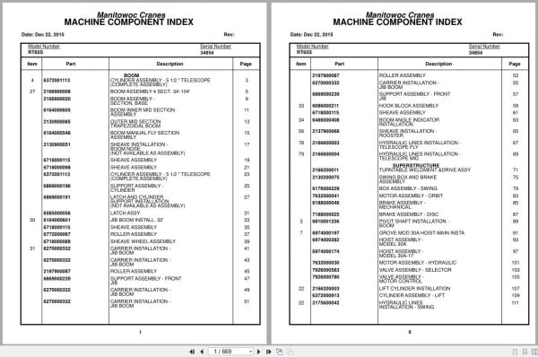
Contents:
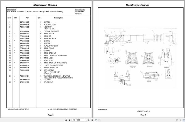
Cylinder Assembly – 5 1/2 ” Telescope (Complete Assembly )
Boom Assembly 4 Sect. 34′-104′
Boom Assembly – Section, Base
Boom Inner Mid Section Assembly
Outer Mid Section Trapezoidal Boom
Boom Manual Fly Section Assembly
Sheave Installation – Boom Nose
Sheave Assembly
Support Assembly – Cylinder
Latch And Cylinder Support Installation
Latch Assy
Jib Boom Install. 32′
Roller Assembly
Sheave Wheel Assembly
Carrier Installation – Jib Boom
Support Assembly – Front Jib
Hook Block Assembly
Boom Angle Indicator Installation
Sheave Installation – Rooster
Hydraulic Lines Installation – Telescope Fly
Hydraulic Lines Installation – Telescope Mid
Turntable Weldment &Drive Assy
Swing Box And Brake Assembly
Box Assembly – Swing
Motor Assembly – Orbit
Brake Assembly – Mechanical
Brake Assembly – Disc
Pivot Shaft Installation – Boom
Grove Mod 30a Hoist-Main Install
Hoist Assembly – Model 30a
Hoist Assembly – Model 30a-17
Motor Assembly – Hydraulic
Valve Assembly – Selector
Valve Assembly – Motor Control
Lift Cylinder Installation
Cylinder Assembly – Lift
Hydraulic Lines Installation – Swing
Hydraulic Lines Installation – Hoist
Emergency Air Tank Install
Elevation And Swing Warning Installation
Switch Assembly – Limit
Control Valve And Linkage Installation
Valve Bank Assembly – 4 Section (A-35 Series)
Valve Section – Inlet (A-35 Series)
Valve Assembly – Outlet
Valve Sub- Assembly – Relief
Cartridge Assembly – Relief Valve
Valve Assembly – 4-Way Section (A-35 Series)
Valve Section – Relief
Valve Assembly – Relief
Valve Section – 4 Way (A-35 Series)
Cartridge Assembly
Valve Bank Assembly – 1 Section (A-20 Series)
Valve Assembly – Section Inlet (A-20 Series)
Valve Assembly – Section Outlet (A-20 Series)
Valve Section – 4 Way
Valve Assembly – Relief 1500 Psi
Valve Bank Assembly – 3 Section (A-20 Series)
Valve Assembly – Relief 2500 Psi
Valve Bank Assembly – 1 Section (A-35 Series)
Hydraulic Shift Converter Line Installation
Lever Lockout Installation
Cylinder Assembly
Hydraulic Lines Installation – Lift
Rotation Ind.Install.
Supply,Press.& Return Hyd.Sch
Cable Follower Installation
Cable Follower Assembly – Hoist
Cable Follower
Follower Installation – Cable
Pin Installation – Turntable Lock
Turntable Installation
Bearing Bolt Installation
Reel Installation – Hose
Hose Reel Assembly – Right Hand
Cab Assembly And Installation
Cab Sub Assembly
Door Assembly
Control Handle Assembly – (Main)
Control Handle Assembly – (Auxiliary)
Control Handle Assembly – (Lift)
Control Handle Assembly (Rear Steering)
Control Handle Assembly – (Mid)
Handle, Control
Handle Control
Controls Installation (Not Available As Assembly )
Pedal Assembly
Valve, Control
Valve Assembly – Control
Valve Assembly – Transmission Shift Control
Valve Assembly
Valve Assembly – Steering
Valve Assembly – Horn
Windshield Wiper Installation
Instruments And Lights Installation
R.H. Side Console Assembly (Front)
R.H. Side Console Assembly – Front
Console Panel Assembly
Panel – Right Hand Side Front
Lock Installation – Window (Not Available As Assembly )
Hydraulic Lines Installation
Heater And Defroster Installation
Acoustical Installation
Extinguisher Installation – Fire
Fire Extinguisher Assembly
Cable Installation – Parking Brake
Cable Assembly – Brake
Axle Installation – Front
Cylinder Assembly – Steer
Rear Axle Installation
Cylinder Assembly -Lockout
Axle Assembly – Rear
Axle Assembly – Drive Steer
Axle Assembly – Drive Steer Housing Assembly
Axle Assembly – Drive Steer Differential And Carrier
Axle Assembly – Drive Steer Hub And Shaft Group
Axle Assembly – Drive Steer Brake Assembly
Axle Assembly – Drive Steer Wedge Assembly
Axle Assembly – Drive Steer Brake Chamber Assembly
Axle Assembly – 3” Steer
Hyd. Outrigger Install.
Cylinder Assembly – Stabilizer
Cylinder Assembly – Outrigger
Outrigger Assembly
Float Assembly – Outrigger
Valve Assembly – 4 Stack Outrigger Solenoid
Valve Assembly – Outrigger Selector (Complete Assembly )
Transmission Installation
Transmission Assembly
Trans. Assy. Case Group
Trans. Clutch & Gear Group
Trans. Low Clutch Group
Trans. Rev.3rd & 2nd Clutch Gr
Trans. Disconnect Group
Trans. Valve Assy. Group
Cummins V-555-C Engine Installation
Cummins V-555-C Engine Assembly
Converter Assembly – Torque
Pump Assembly – Steer
Throttle Installation – Cummins V-555-C
Cylinder Assembly – Throttle
Pump And Disconnect Installation – 4 Stage
Disconnect Assembly – Pump (Not Available As Assembly )
Pump Assembly
Radiator And Oil Cooler Installation
Cleaner Installation – Air
Cleaner Assembly – Air
Exhaust System Installation
Hood Assembly – Engine
Quick Start Installation (Not Available As Assembly )
Wiring Diagram – Hourmeter
Filter Assembly – Oil
Clutch/Lube Oil Pressure Check Point Installation
Air Brake And Throttle Lines Installation
Valve Assembly – Check
Standard Wiring Diagram
Decal Installation – Rt65s/75s

REALEASE :
REALEASE :

REALEASE :
REALEASE :

REALEASE :
REALEASE :

REALEASE :
REALEASE :

REALEASE :
REALEASE :

REALEASE :
REALEASE :

REALEASE :
REALEASE :

REALEASE :
REALEASE :
Automotive - Heavy Equipment - Truck & Bus - Forklift - Crane