")
Expert Support
Full Speed
100% Working
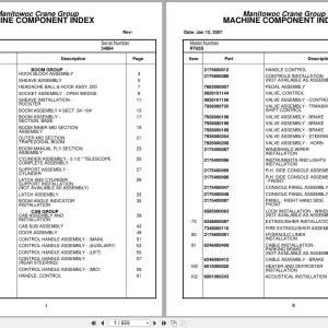
Grove Crane RT65S 34884 Parts Manual 2007
15 USD
- Description
Description
Contents:
Hook Block Assembly
Sheave Assembly
Headache Ball & Hook Assy. 200
Socket Assembly – Open Wedge
Sheave Installation – Rooster
Boom Assembly 4 Sect. 34’-104’
Boom Assembly – Section, Base
Boom Inner Mid Section Assembly
Outer Mid Section Trapezoidal Boom
Boom Manual Fly Section Assembly
Cylinder Assembly – 5 1/2 ” Telescope Complete Assembly
Support Assembly – Cylinder
Latch And Cylinder Support Installation
Latch Assembly
Boom Angle Indicator Installation
Cab Assembly And Installation
Cab Sub Assembly
Door Assembly
Control Handle Assembly – (Main)
Control Handle Assembly – (Auxiliary)
Control Handle Assembly – (Lift)
Control Handle Assembly (Rear Steering)
Control Handle Assembly – (Mid)
Handle, Control
Handle Control
Controls Installation (Not Available As Assembly )
Pedal Assembly
Valve, Control
Valve Assembly – Control
Valve Assembly – Transmission Shift Control
Valve Assembly – Brake
Valve Assembly – Steering
Valve Assembly – Horn
Windshield Wiper Installation
Instruments And Lights Installation
R.H. Side Console Assembly (Front)
R.H. Side Console Assembly – Front
Console Panel Assembly
Panel – Right Hand Side Front
Lock Installation – Window (Not Available As Assembly )
Extinguisher Installation – Fire
Fire Extinguisher Assembly
Hydraulic Lines Installation
Cable Installation – Parking Brake
Cable Assembly – Brake
Heater And Defroster Installation
Acoustical Installation
Hydraulic Lines Installation – Swing
Hydraulic Lines Installation – Lift
Hydraulic Lines Installation – Telescope Fly
Hydraulic Lines Installation – Telescope Mid
Control Valve And Linkage Installation
Valve Bank Assembly – 4 Section (A-35 Series)
Valve Section – Inlet (A-35 Series)
Valve Assembly – Outlet
Valve Sub- Assembly – Relief
Cartridge Assembly – Relief Valve
Valve Assembly – 4-Way Section (A-35 Series)
Valve Section – Relief
Valve Assembly – Relief
Valve Section – 4 Way (A-35 Series)
Cartridge Assembly
Valve Bank Assembly – 1 Section (A-20 Series)
Valve Assembly – Section Inlet (A-20 Series)
Valve Assembly – Section Outlet (A-20 Series)
Valve Section – 4 Way
Valve Assembly – Relief 1500 Psi
Valve Bank Assembly – 3 Section (A-20 Series)
Valve Assembly – Relief 2500 Psi
Valve Bank Assembly – 1 Section (A-35 Series)
Main Hoist Install. Mod.30
Hoist Assembly
Group Assembly – Left Hand (Not Available As Assembly )
Group Assembly – Right Hand (Not Available As Assembly )
Motor Assembly – Hydraulic
Valve Assembly – Selector
Hydraulic Lines Installation – Main And Auxiliary Hoist
Manifold Installation – Hydraulic
Lift Cylinder Installation
Cylinder Assembly – Lift
Emergency Air Tank Install
Elevation And Swing Warning Installation
Switch Assembly – Limit
Pin Installation – Turntable Lock
Pivot Shaft Installation – Boom
Swivel Installation
Swivel Assembly
Swivel Assembly – Hydraulic
Swivel Assembly – 10 Port
Ring Assembly – Slip
Bearing Bolt Installation
Turntable Installation
Swing Box And Brake Assembly
Box Assembly – Swing
Motor Assembly – Orbit
Brake Assembly – Mechanical
Brake Assembly – Disc
Reel Installation – Hose
Hose Reel Assembly – Right Hand
Storage Installation – Removable Windshield
Throttle Installation – Cummins V-555-C
Cylinder Assembly – Throttle
Pump Disconnect & Cover Install
Transmission Installation
Transmission Assembly
Transmission Assembly Valve Assembly –
Driveline Assembly
Front Driveline Installation
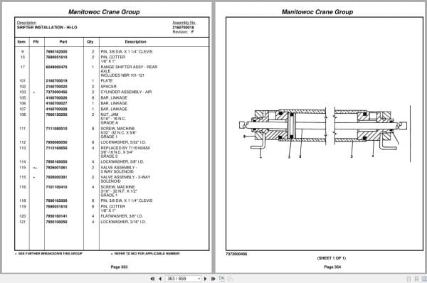
Shifter Installation – Hi-Lo
Cylinder Assembly – Air
Valve Assembly – 3 Way Solenoid
Hydraulic Shift Converter Line Installation
Axle Installation – Front
Cylinder Assembly – Steer
Rear Axle Installation
Cylinder Assembly -Lockout
Axle Assembly – Rear
Axle Assembly – Drive/Steer
Axle Assembly – 3’’ Steer
Tire And Wheel Assembly
Hyd. Outrigger Install.
Cylinder Assembly – Stabilizer
Cylinder Assembly – Outrigger
Outrigger Assembly
Float Assembly – Outrigger
Valve Assembly – 4 Stack Outrigger Solenoid
Valve Assembly – Outrigger Selector Complete Assembly
Fuel Tank,Batt.Box &Cover Inst
Air Tanks, Valves, And Cover Installation
Valve Assembly – Quick Release
Valve Assembly – Relay
Front Deck Cover And Storage Well Installation
Terminal Block Assembly – Electrical
Light And Turn Signal Installation
Fenders And Storage Well Assembly And Installation
Pintle Hook Installation
Pintle Hook Assembly
Hyd Lines-Supply,Press& Return
Decal Installation – Rt65s/75s
Rear View Mirror Installation
Hydraulic Reservoir And Deck Installation
Hydraulic Reservoir And Deck Assembly
Alarm Installation – Back-Up
Air Brake And Throttle Lines Installation
Valve Assembly – Check
Cover And Handle Assembly – Hydraulic Pump Disconnect
Air Brake And Throttle Line Installation
Valve Install.Front & Rear O/R
Valve Installation – Rear Axle Lockout
Valve Installation – Front Steer
Transmission And Converter Lines Installation
Hydraulic Lines Installation – Outrigger
Valve, Pressure Relief
Front Steering – (Hydraulic Schematic)
Hydraulic Lines Installation – Rear Steer
Axle Lockout – Hydraulic Schematic
Standard Wiring Diagram
Alphabetical Index
Recommended Spare Parts List
Foot Note Index
Related Products
-
Grove Parts Document Crane 7.82 Gb TM TMS TT TTS Series Collection PDF
Original price was: 400.250Current price is: 250. USD -
Grove Crane 1.8 Gb YB Series Collection Parts Document PDF
Original price was: 300.70Current price is: 70. USD -
Grove GMK EPC Spare Part Catalog Manual 2023 PDF EN DE
Original price was: 600.70Current price is: 70. USD -
Grove RT EPC Spare Parts Catalog Manual 2023 PDF EN
Original price was: 2,000.540Current price is: 540. USD -
Grove Crane AT ATS Series Collection Parts Document PDF 447 MB
Original price was: 400.70Current price is: 70. USD -
Grove Crane 2024 Collection Parts Document 72.1 GB PDF
Original price was: 1,200.840Current price is: 840. USD -
Grove Crane RT GRT Series Collection Parts Document PDF 43 GB
Original price was: 500.340Current price is: 340. USD -
Grove Parts Document Crane GMK Series Collection 17.1 GB PDF
Original price was: 500.290Current price is: 290. USD