
0 ITEMSVIEW CART

✓
Expert Support
✓
Full Speed
✓
100% Working
Grove Crane RT65S 38023 Parts Manual 2016
Size: 5.46 MB
Format: PDF
Language: English
Brand: Grove
Type of Machine: Crane
Type of Manual: Parts Manual
Model: Grove RT65S Crane
Serial Number: 38023
Publication Date: 2016
Number of Pages: 829 Pages
30 USD
- Description
Description
Contents:
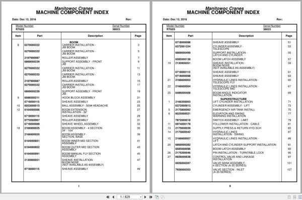
Carrier Installation – Jib Boom
Roller Assembly
Support Assembly – Front Jib
Hook Block Assembly
Sheave Assembly
Ball Assembly – 500# Headache
Boom Extension Installation – 32′
Sheave Wheel Assembly
Boom Assembly – 4 Section 34′ – 104′
Boom Assembly – Section, Base
Boom Inner Mid Section Assembly
Boom Outer Mid Section Assembly
Boom Manual Fly Section Assembly
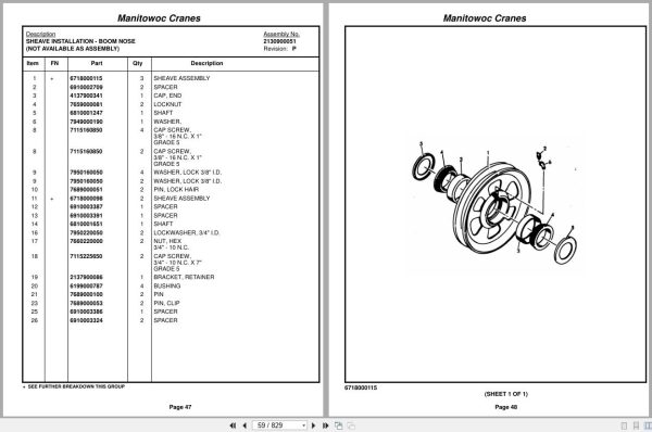
Sheave Installation – Boom Nose
Cylinder Assembly – Telescope
Support Installation – Latch And Cylinder
Boom Latch Assembly
Hydraulic Lines Installation – Telescope Fly
Hydraulic Lines Installation – Telescope Mid
Boom Angle Indicator Installation
Lift Cylinder Installation
Cylinder Assembly – Lift
Emergency Air Tank Install
Elevation And Swing Warning Installation
Switch Assembly – Limit
Follower Installation – Cable
Supply,Press.& Return Hyd.Sch
Hydraulic Lines Installation – Swing
Hydraulic Lines Installation – Lift
Latch And Cylinder Support Installation
Pin Installation – Turntable Lock
Control Valve And Linkage Installation
Valve Bank Assembly – 4 Section (A-35 Series)
Valve Section – Inlet (A-35 Series)
Valve Assembly – Outlet
Valve Sub- Assembly – Relief
Cartridge Assembly – Relief Valve
Valve Assembly – 4-Way Section (A-35 Series)
Valve Section – Relief
Valve Assembly – Relief
Valve Section – 4 Way (A-35 Series)
Cartridge Assembly
Valve Bank Assembly – 1 Section (A-20 Series)
Valve Assembly – Section Inlet (A-20 Series)
Valve Assembly – Section Outlet (A-20 Series)
Valve Section – 4 Way
Valve Assembly – Relief 1500 Psi
Valve Bank Assembly – 3 Section (A-20 Series)
Valve Assembly – Relief 2500 Psi
Valve Bank Assembly – 1 Section (A-35 Series)
Pivot Shaft Installation – Boom
Hydraulic Lines Installation – Main And Auxiliary Hoist
Bearing Bolt Installation
Turntable Installation
Swing Box And Brake Assembly
Box Assembly – Swing
Motor Assembly – Orbit
Brake Assembly – Mechanical
Brake Assembly – Disc
Reel Installation – Hose
Hose Reel Assembly – Right Hand
Hydraulic Shift Converter Line Installation
Hoist Installation – Model 15a
Hoist Assembly – Model 15a-16
Gear Reduction Assembly
Motor Assembly – Hydraulic
Tubing Installation
Idler Drum Installation (Not Available As Assembly )
Roller Assembly – Cable
Counterweight Installation (Not Available As Assembly )
Tubing Installation – Hoist
Valve Assembly – Hoist Control
Rotation Indicator Inst. Main
Rotation Indicator Assembly -Hoist Drum
Rotation Indicator Install.
Support Installation – Hoist Tube
Grove Mod 30a Hoist-Main Insta
Hoist Assembly – Model 30a
Hoist Assembly – Model 30a-17
Valve Assembly – Selector
Valve Assembly – Motor Control
Manifold Installation – Hydraulic
Swivel Installation
Swivel Assembly
Swivel Assembly – Hydraulic
Swivel Assembly – 10 Port
Ring Assembly – Slip
Cab Assembly And Installation
Cab Sub Assembly
Door Assembly
Control Handle Assembly – (Main)
Control Handle Assembly – (Auxiliary)
Control Handle Assembly – (Lift)
Control Handle Assembly (Rear Steering)
Control Handle Assembly – (Mid)
Handle, Control
Handle Control
Controls Installation (Not Available As Assembly )
Pedal Assembly
Valve, Control
Valve Assembly – Control
Valve Assembly – Transmission Shift Control
Valve Assembly
Valve Assembly – Steering
Valve Assembly – Horn
Windshield Wiper Installation
Instruments And Lights Installation
R.H. Side Console Assembly (Front)
R.H. Side Console Assembly – Front
Console Panel Assembly
Panel – Right Hand Side Front
Lock Installation – Window (Not Available As Assembly )
Extinguisher Installation – Fire
Fire Extinguisher Assembly
Hydraulic Lines Installation
Cable Installation – Parking Brake
Cable Assembly – Brake
Cover Installation
Acoustical Installation
Storage Installation – Removable Windshield
Air Brake And Throttle Lines Installation
Valve Assembly – Check
Lug Nut And Washer Installation
Axle Installation – Front
Cylinder Assembly – Steer
Rear Axle Installation
Cylinder Assembly -Lockout
Axle Assembly – Rear
Axle Assembly – Drive Steer
Axle Assembly – Drive Steer Housing Assembly
Axle Assembly – Drive Steer Differential And Carrier
Axle Assembly – Drive Steer Hub And Shaft Group
Axle Assembly – Drive Steer Brake Assembly
Axle Assembly – Drive Steer Wedge Assembly
Axle Assembly – Drive Steer Brake Chamber Assembly
Axle Assembly – 3” Steer
Hyd. Outrigger Install.
Cylinder Assembly – Stabilizer
Cylinder Assembly – Outrigger
Outrigger Assembly
Float Assembly – Outrigger
Valve Assembly – 4 Stack Outrigger Solenoid
Valve Assembly – Outrigger Selector (Complete Assembly )
Transmission Installation
Transmission Assembly
Trans. Assy. Case Group
Trans. Clutch & Gear Group
Trans. Low Clutch Group
Trans. Rev.3rd & 2nd Clutch Gr
Trans. Disconnect Group
Trans. Valve Assy. Group
Cat 3208 Engine Install
Cat 3208 Engine Assy
Converter Assembly – Torque
Pump Assembly – Steer
Cylinder Assembly – Throttle
Pump And Disconnect Installation – 4 Stage
Disconnect Assembly – Pump (Not Available As Assembly )
Pump Assembly
Radiator And Oil Cooler Installation
Hood Assembly – Engine
Exhaust System Installation
Cleaner Installation – Air (Not Available As Assembly )
Cleaner Assembly – Air
Quick Start Installation (Not Available As Assembly )
Clutch/Lube Oil Pressure Check Point Installation
Filter Assembly – Oil
Filter Assembly – Primary Fuel
Driveline Installation
Driveline (Front Axle)
Driveline Assembly
Driveline (Rear Axle)
Driveline (Transmission)
Fuel Tank,Batt.Box &Cover Inst
Air Tanks, Valves, And Cover Installation
Valve Assembly – Quick Release
Valve Assembly – Relay
Valve Install.Front & Rear O/R
Tire And Wheel Assembly
Shifter Installation – Hi-Lo
Cylinder Assembly – Air
Valve Assembly – 3 Way Solenoid
Front Deck Cover And Storage Well Installation
Terminal Block Assembly – Electrical
Valve Installation – Rear Axle Lockout
Valve Installation – Front Steer
Transmission And Converter Lines Installation
Light And Turn Signal Installation
Fenders And Storage Well Assembly And Installation
Pintle Hook Installation
Pintle Hook Assembly
Hydraulic Lines Installation – Outrigger
Valve, Pressure Relief
Front Steering – (Hydraulic Schematic)
Hydraulic Lines Installation – Rear Steer
Axle Lockout – Hydraulic Schematic
Rear View Mirror Installation
Hydraulic Reservoir And Deck Installation
Hydraulic Reservoir And Deck Assembly
Cover And Handle Assembly – Hydraulic Pump Disconnect
Air Brake And Throttle Line Installation
Standard Wiring Diagram
Decal Installation – Rt65s/75s
Related Products
-
Grove GMK EPC Spare Part Catalog Manual 2023 PDF EN DE
Original price was: 600.70Current price is: 70. USDThis is an offline spare parts catalog, you need to use this to sell the spare parts and it can help you a little with assembly. It’s from a manufacturer and the best in the world.Hot-88%
REALEASE :
REALEASE :
-
Grove RT EPC Spare Parts Catalog Manual 2023 PDF EN
Original price was: 2,000.540Current price is: 540. USDThis is an offline spare parts catalog, you need to use this to sell the spare parts and it can help you a little with assembly. It’s from a manufacturer and the best in the world.Hot-73%
REALEASE :
REALEASE :
-
Grove Parts Document Crane GMK Series Collection 17.1 GB PDF
Original price was: 500.290Current price is: 290. USDThis is an offline spare parts catalog, you need to use this to sell the spare parts and it can help you a little with assembly. It’s from a manufacturer and the best in the world.Hot-42%
REALEASE :
REALEASE :
-
Grove Parts Document Crane 7.82 Gb TM TMS TT TTS Series Collection PDF
Original price was: 400.250Current price is: 250. USDThis is an offline spare parts catalog, you need to use this to sell the spare parts and it can help you a little with assembly. It’s from a manufacturer and the best in the world.Hot-38%
REALEASE :
REALEASE :
-
Grove Crane AT ATS Series Collection Parts Document PDF 447 MB
Original price was: 400.70Current price is: 70. USDIf you are a technician, You will need to use this product to repair your vehicleHot-83%
REALEASE :
REALEASE :
-
Grove Crane RT GRT Series Collection Parts Document PDF 43 GB
Original price was: 500.340Current price is: 340. USDThis is an offline spare parts catalog, you need to use this to sell the spare parts and it can help you a little with assembly. It’s from a manufacturer and the best in the world.Hot-32%
REALEASE :
REALEASE :
-
Grove Crane 2024 Collection Parts Document 72.1 GB PDF
Original price was: 1,200.840Current price is: 840. USDThis is an offline spare parts catalog, you need to use this to sell the spare parts and it can help you a little with assembly. It’s from a manufacturer and the best in the world.Hot-30%
REALEASE :
REALEASE :
-
Grove Crane 1.8 Gb YB Series Collection Parts Document PDF
Original price was: 300.70Current price is: 70. USDThis is an offline spare parts catalog, you need to use this to sell the spare parts and it can help you a little with assembly. It’s from a manufacturer and the best in the world.Hot-77%
REALEASE :
REALEASE :