
3 ITEMSVIEW CART


Total: 220.00
Expert Support
Full Speed
100% Working
15 USD
Contents:
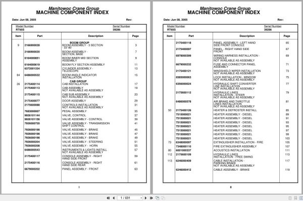
Boom Assembly – 3 Section – 33’-80’
Boom Assembly – Section, Base
Boom Inner Mid Section Assembly
Boom Fly Section Assembly
Cylinder Assembly – Telescope
Boom Angle Indicator Installation
Cab Installation
Cab Assembly Not Available As Assembly
Cab Sub Assembly Not Available As Assembly
Door Assembly
Controls Installation Not Available As Assembly
Pedal Assembly
Valve, Control
Valve Assembly – Control
Valve Assembly – Transmission Shift Control
Valve Assembly – Brake
Valve Assembly – Steering
Valve Assembly – Horn
Instruments & Lights Install Not Available As Assembly
Console Assembly – Right Hand Side Front
Console Assembly – Right Hand Side Rear
Panel Assembly – Front
Panel Assembly – Left Hand Side Front Console
Panel – Right Hand Side Front
Wiring Harness Installation – Console
Fuse And Connector Panel Assembly
Windshield Wiper Installation Not Available As Assembly
Lock Installation – Window Not Available As Assembly
Hydraulic Shift Converter Line Installation
Hydraulic Lines Installation – Steer
Air Brake And Throttle Lines Installation
Heater & Defroster Install
Heater Assembly – Diesel
Extinguisher Installation – Fire
Fire Extinguisher Assembly
Acoustics Installation
Hydraulic Lines Installation – Free Swing
Cable Installation – Parking Brake
Cable Assembly – Brake
Valve Installation – Control
Valve Bank Assembly – 4 Section (A-35 Series)
Valve Section – Inlet (A-35 Series)
Valve Assembly – Outlet
Valve Sub- Assembly – Relief
Cartridge Assembly – Relief Valve
Valve Assembly – 4-Way Section (A-35 Series)
Valve Section – Relief
Valve Assembly – Relief
Valve Section – 4 Way (A-35 Series)
Cartridge Assembly
Valve Bank Assembly – 1 Section (A-20 Series)
Valve Assembly – Section Inlet (A-20 Series)
Valve Assembly – Section Outlet (A-20 Series)
Valve Section – 4 Way
Valve Assembly – Relief 1500 Psi
Valve Bank Assembly – 3 Section (A-20 Series)
Valve Assembly – Relief 2500 Psi
Valve Bank Assembly – 1 Section (A-35 Series)
Supply,Press.& Return Hyd.Sch
Hydraulic Lines Installation – Swing
Hydraulic Lines Installation – Lift
Hydraulic Lines Installation – Telescope Mid
Hydraulic Lines Installation – Telescope Fly
Hydraulic Lines Installation – Main Hoist
Grove Mod 30a Hoist-Main Insta
Hoist Assembly – Model 30a
Hoist Assembly – Model 30a-17
Motor Assembly – Hydraulic
Valve Assembly – Selector
Valve Assembly – Motor Control
Follower Installation – Cable
Rotation Indicator Inst. Main
Rotation Indicator Assembly -Hoist Drum
Support Installation – Tube
Turntable Installation
Drive Install – Turntable
Swing Box And Brake Assembly
Box Assembly – Swing
Motor Assembly – Orbit
Brake Assembly – Mechanical
Brake Assembly – Disc
Swivel Assembly And Installation
Swivel Assembly – Hydraulic
Swivel Assembly – 10 Port
Ring Assembly – Slip 32 Conductor
Manifold Installation – Hydraulic
Lift Cylinder Installation
Cylinder Assembly – Lift
Counterweight Install.Mod.#30a
Reel Installation – Hose
Hose Reel Assembly – Right Hand
Elevation And Swing Warning Installation
Switch Assembly – Limit
Turntable Lock Pin Installation Installation
Pivot Shaft Installation – Boom
Bearing Bolt Installation
Storage Installation – Removable Windshield
Engine Install Gmc 6v-53n
Hood Assembly – Engine
Filter Assembly – Oil
Torque Converter Assembly
Fitting Assy
Pump Assembly – Steer
Wiring Diagram
Wiring Diagram – Hourmeter
Transmission Installation
Transmission Assembly
Transmission Assembly Valve Assembly –
Driveline Installation
Driveline (Front Axle)
Driveline Assembly
Driveline (Rear Axle)
Driveline (Transmission)
Shifter Installation – Hi-Lo
Cylinder Assembly – Air
Valve Assembly – 3 Way Solenoid
Transmission And Converter Lines Installation
Axle Installation – Front
Cylinder Assembly – Steer
Rear Axle Installation
Cylinder Assembly -Lockout
Axle Assembly – Rear
Axle Assembly – Drive/Steer
Axle Assembly – 3’’ Steer
Tire & Wheel Assy.
Valve Installation – Rear Axle Lockout
Valve Installation – Front Steer
Rear Axle Lockout Override Installation
Valve Assembly – Solenoid
Hydraulic Lines Installation – Front Steer
Hydraulic Lines Installation – Rear Steer
Hydraulic Lines Installation – Axle Lockout With Override
Lug Nut And Washer Installation
Hyd. Outrigger Install.
Cylinder Assembly – Stabilizer
Cylinder Assembly – Outrigger
Outrigger Assembly
Float Assembly – Outrigger
Valve Assembly – 4 Stack Outrigger Solenoid
Valve Install.Front & Rear O/R
Hydraulic Lines Installation – Outrigger
Valve, Pressure Relief
Hydraulic Reservoir And Deck Installation
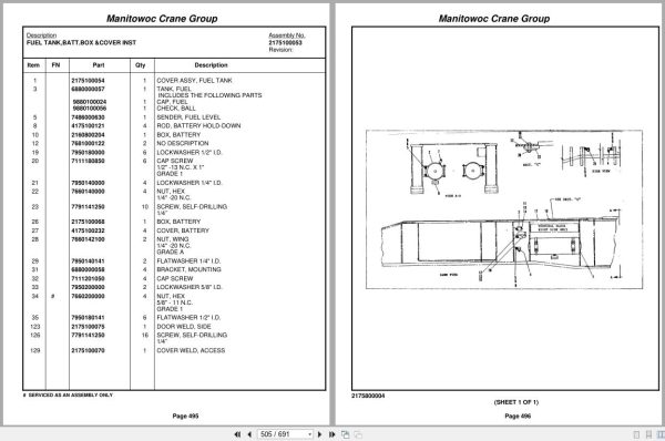
Fuel Tank,Batt.Box &Cover Inst
Air Tanks, Valves, And Cover Installation
Valve Assembly – Quick Release
Valve Assembly – Relay
Light And Turn Signal Installation
Fenders And Storage Well Assembly And Installation
Decal Installation – Rt65s/75s
Rear View Mirror Installation
Cover And Handle Assembly – Hydraulic Pump Disconnect
Air Brake And Throttle Line Installation
Valve Assembly – Check
Air Brake & Throttle Lines Ins

REALEASE :
REALEASE :

REALEASE :
REALEASE :

REALEASE :
REALEASE :

REALEASE :
REALEASE :

REALEASE :
REALEASE :

REALEASE :
REALEASE :

REALEASE :
REALEASE :

REALEASE :
REALEASE :
 Automotive - Heavy Equipment - Truck & Bus - Forklift - Crane