
0 ITEMSVIEW CART

✓
Expert Support
✓
Full Speed
✓
100% Working
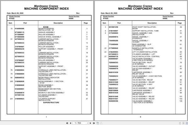
Grove Crane RT65S 44996 Parts Manual 2020
Size: 4.91 MB
Format: PDF
Language: English
Brand: Grove
Type of Machine: Crane
Type of Manual: Parts Manual
Model: Grove RT65S Crane
Serial Number: 44996
Publication Date: 2020
Number of Pages: 703 Pages
40 USD
- Description
Description
Contents:
Boom Extension Installation – 32′
Sheave Assembly
Roller Assembly
Sheave Wheel Assembly
Carrier Installation -Boom Extension
Support Assembly – Front Jib
Hydraulic Lines Installation -Telescope Fly
Hydraulic Lines Installation -Telescope Mid
Boom Angle Indicator Installation
Boom Assembly – 3 Section- 33′-80′
Boom Assembly -Section, Base
Boom Inner Mid Section Assembly
Boom Fly Section Assembly
Cylinder Assembly -Telescope
Cylinder Support Installation
Pivot Shaft Installation -Boom
Support Installation – Tube
Swivel Assembly And Installation
Swivel Assembly -Hydraulic
Swivel Assembly -10 Port
Ring Assembly – Slip32 Conductor
Manifold Installation – Hydraulic
Lift Cylinder Installation
Cylinder Assembly – Lift
Valve Installation – Control
Valve Bank Assembly -4 Section (A-35 Series)
Valve Section – Inlet(A-35 Series)
Valve Assembly – Outlet
Valve Sub- Assembly -Relief
Cartridge Assembly -Relief Valve
Valve Assembly – 4-Way Section(A-35 Series)
Valve Section – Relief
Valve Assembly – Relief
Valve Section – 4 Way(A-35 Series)
Cartridge Assembly
Valve Bank Assembly -1 Section (A-20 Series)
Valve Assembly – Section Inlet (A-20 Series)
Valve Section – 4 Way
Valve Assembly – Relief1500 Psi
Valve Bank Assembly -3 Section (A-20 Series)
Valve Assembly – Relief2500 Psi
Valve Bank Assembly -1 Section (A-35 Series)
Hoist Installation – Main
Hoist Assembly -Model Ho30b-16
Motor Assembly , Hydraulic
Valve Assembly – Selector
Valve Assembly -Motor Control
Emergency Air Tank Installation
Elevation And Swing Warning Installation
Switch Assembly – Limit
Hydraulic Shift Converter Line Installation
Rotation Indicator Installation
Driver Assembly driver Assembly
Indicator Assembly
Transmitter Assembly
Hydraulic Lines Installation -Lift
Pin Installation – Turntable Lock Installation
Free Swing – Hydraulic Schematic
Follower Installation – Cable
Hydraulic Lines Installation -Main Hoist
Counterweight Install.Mod.#30a
Bearing Bolt Installation
Reel Installation – Hose
Hose Reel Assembly -Right Hand
Solenoid Valve & Flow Divider Installation (Free Swing
Valve Assembly – Solenoid
Turntable Section& Drive Assy
Swing Box And Brake Assembly
Motor Assembly – Orbit
Brake Assembly
Supply, Pressure And Return(Free Swing)
Cab Installation
Cab Sub- Assembly And Installation
Door Assembly
Controls Installation (Not Available As Assembly )
Pedal Assembly
Valve, Control
Valve Assembly – Control
Valve Assembly – Transmission Shift Control
Valve Assembly
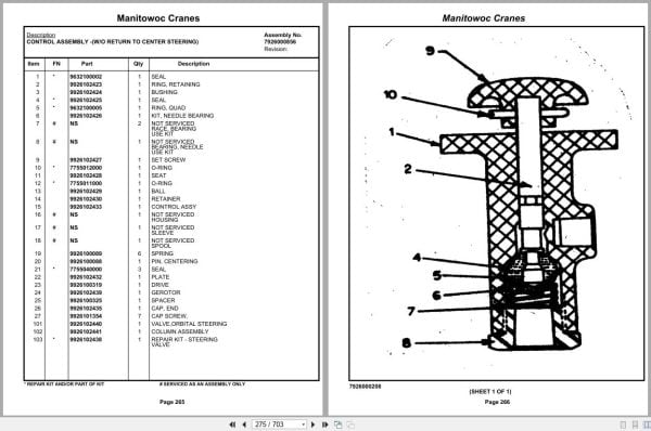
Control Assembly -(W/O Return To Center Steering)
Valve Assembly – Horn
Instruments And Lights Installation
Console Assembly – Righthand Side Rear
Panel Assembly – Front
Panel – Right Hand Side Front
Wiring Harness Installation -Cab
Fuse And Connector Panel Assembly
Air Brake And Throttle Lines Installation
Seat Assembly
Brake Pedal And Hydrauliclines Installation
Valve Installation -Solenoid And Pressure
Extinguisher Installation – Fire
Fire Extinguisher Assembly
Acoustical Installation
Valve Assembly – Check
Sk780848
Defroster Installation – Heater And
Sk780592
Heater
Fan Installation – Cab
Axle Installation – Front
Cylinder Assembly – Steer
Outrigger And Valve- Installation
Cylinder Assembly -Stabilizer
Cylinder Assembly -Outrigger
Transmission Installation
Transmission Assembly
Trans. Assy. Case Group
Trans. Clutch & Gear Group
Trans. Low Clutch Group
Trans. Rev.3rd & 2nd Clutch Gr
Trans. Disconnect Group
Trans. Valve Assy. Group
Driveline Installation
Driveline (Front Axle)
Driveline Assembly
Driveline (Rear Axle)
Driveline (Transmission)
Hydraulic Reservoir And Deck Installation
Reservoir And Deck Assembly
Filter Assembly – Oil
Fuel Tank, Battery Box,And Cover Installation
Front Deck Cover Andstorage Well Installation
Air Tanks, Valves, And Cover Installation
Valve Assembly -Quick Release
Valve Assembly – Relay
Valve Installation -Rear Axle Lockout
Valve Installation -Front Steer
Transmission And Converter Lines Installation
Shifter Installation -Hi-Lo
Cylinder Assembly – Air
Valve Assy. Three Way
Rear Axle Lockout Override Installation
Tire And Wheel Assembly
Light And Turn Signal Installation
Fenders And Storage Well Assembly And Installation
Hydraulic Lines Installation -Axle Lockout With Override
Indicator Installation -Rear Steer
Hydraulic Lines Installation -Outrigger
Valve, Pressure Relief
Front Steer – Hydraulic Schematic
Rear Steer – Hydraulic Schematic
Alarm Installation -Back-Up
Rear View Mirror Installation
Float Assembly – Outrigger
Wiring Harness Installation – Carrier
Air Brake And Throttle Line Installation
Axle Installation – Rear
Axle Assembly – Drive Steer
Axle Assembly – Drive Steerhousing Assembly
Axle Assembly – Drive Steerdifferential And Carrier
Axle Assembly – Drive Steerhub And Shaft Group
Axle Assembly – Drive Steerbrake Assembly
Axle Assembly – Drive Steerwedge Assembly
Axle Assembly – Drive Steerbrake Chamber Assembly
Cylinder Assembly -Lockout
Engine Installation -Cummins V-555
Radiator And Oil Cooler Installation
Cleaner Installation – Air
Cleaner Assembly – Air
Exhaust System Installation
Hood Assembly – Engine
Quick Start Installation (Not Available As Assembly )
Clutch/Lube Oil Pressure Check Point Installation
Torque Converter Assembly
Fitting Assy
Pump Assembly – Steer
Wiring Diagram – Hourmeter
Engine Harness Installation
Throttle Installation -Cummins V-555-C
Cylinder Assembly – Throttle
Pump And Disconnect Installation – 4 Stage
Disconnect Assembly – Pump(Not Available As Assembly )
Pump Assembly
Lug Nut And Washer Installation
Wiring Diagram
Decal Installation -Rt65s/75s
Related Products
-
Grove RT EPC Spare Parts Catalog Manual 2023 PDF EN
Original price was: 2,000.540Current price is: 540. USDThis is an offline spare parts catalog, you need to use this to sell the spare parts and it can help you a little with assembly. It’s from a manufacturer and the best in the world.Hot-73%
REALEASE :
REALEASE :
-
Grove Crane RT GRT Series Collection Parts Document PDF 43 GB
Original price was: 500.340Current price is: 340. USDThis is an offline spare parts catalog, you need to use this to sell the spare parts and it can help you a little with assembly. It’s from a manufacturer and the best in the world.Hot-32%
REALEASE :
REALEASE :
-
Grove Parts Document Crane GMK Series Collection 17.1 GB PDF
Original price was: 500.290Current price is: 290. USDThis is an offline spare parts catalog, you need to use this to sell the spare parts and it can help you a little with assembly. It’s from a manufacturer and the best in the world.Hot-42%
REALEASE :
REALEASE :
-
Grove Parts Document Crane 7.82 Gb TM TMS TT TTS Series Collection PDF
Original price was: 400.250Current price is: 250. USDThis is an offline spare parts catalog, you need to use this to sell the spare parts and it can help you a little with assembly. It’s from a manufacturer and the best in the world.Hot-38%
REALEASE :
REALEASE :
-
Grove Crane 1.8 Gb YB Series Collection Parts Document PDF
Original price was: 300.70Current price is: 70. USDThis is an offline spare parts catalog, you need to use this to sell the spare parts and it can help you a little with assembly. It’s from a manufacturer and the best in the world.Hot-77%
REALEASE :
REALEASE :
-
Grove Crane 2024 Collection Parts Document 72.1 GB PDF
Original price was: 1,200.840Current price is: 840. USDThis is an offline spare parts catalog, you need to use this to sell the spare parts and it can help you a little with assembly. It’s from a manufacturer and the best in the world.Hot-30%
REALEASE :
REALEASE :
-
Grove GMK EPC Spare Part Catalog Manual 2023 PDF EN DE
Original price was: 600.70Current price is: 70. USDThis is an offline spare parts catalog, you need to use this to sell the spare parts and it can help you a little with assembly. It’s from a manufacturer and the best in the world.Hot-88%
REALEASE :
REALEASE :
-
Grove Crane AT ATS Series Collection Parts Document PDF 447 MB
Original price was: 400.70Current price is: 70. USDIf you are a technician, You will need to use this product to repair your vehicleHot-83%
REALEASE :
REALEASE :