
1 ITEMVIEW CART

Total: 10.00
Expert Support
Full Speed
100% Working
15 USD
Contents:
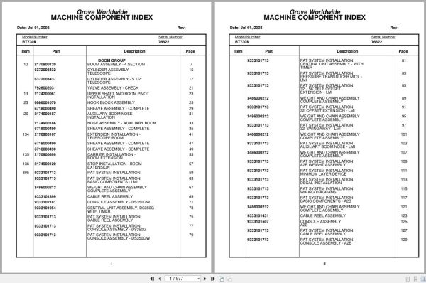
Grove Worldwide
Boom Assembly – 4 Section
Cylinder Assembly – Telescope
Cylinder Assembly – 5 1/2″ Telescope
Valve Assembly – Check
Upper Shaft And Boom Pivot Installation
Hook Block Assembly
Sheave Assembly – Complete
Auxiliary Boom Nose Installation
Nose Assembly – Auxiliary Boom
Extension Installation – Telescope Boom
Carrier Installation – Boom Extension
Stop Installation – Boom Extension
Pat System Installation
Pat System Installation Basic Components – Lmi
Weight And Chain Assembly Complete Assembly
Cable Reel Assembly
Console Assembly – Ds350gw
Central Unit Assembly , Ds350g With Timer
Pat System Installation Cable Reel Assembly
Pat System Installation Console Assembly – Ds350g
Pat System Installation Console Assembly – Ds350gw
Pat System Installation Central Unit Assembly – With
Pat System Installation Pressure Transducer Mtg –
Pat System Installation 32’ – 56’ Tele Offset
Pat System Installation 32’ Offset Extension – Lmi
Pat System Installation 32’ Swing Away – Lmi
Pat System Installation Auxiliary Boom Nose – Lmi
Pat System Installation A2b Weight Assembly
Pat System Installation Minimum Layer Device
Pat System Installation Decal Installation
Pat System Installation Wiring Diagrams
Pat System Installation Basic Components – A2b
Console Assembly A2b
Pat System Installation Console Assembly – A2b
Pat System Installation 32’ Offset Extension – A2b
Pat System Installation 32’ Swing Away – A2b
Pat System Installation Auxiliary Boom Nose – A2b
Pat System Installation Minimum Layer
Sk871671
Sheave Installation
Electrical System Installation
Harness Assembly – Superstructure
Electrical System – Cab
Cab Installation
Valve Assembly – Treadle
Cable Assembly – Control
Valve Assembly – Steering Control
Column Assembly – Steering
Steering Wheel Assembly
Fan Assembly – 12 Volt Cab
Fire Extinguisher Assembly
Door Assembly – Cab
Console Installation – Front
Shift Control – Three Speed
Control Handles Installation
Rotation Indicator Assembly
Mirror Installation – Cab
Pedal Installation – Swing Brake
Hydraulic Heater Installation
Blower Fan Assembly
Harness Assembly – Heater
Valve Assembly – Heater
Pump Installation – Heater
Pump Assembly – Heater
Reservoir Assembly – Power Steering
Lockout Switch Installation – Rear Axle
Control Seat Installation
Seat Assembly – Control
Seat Assembly
Valve Assembly – Joy Stick
Floor Mat Installation
Pedal And Valve Installation – Telescope
Valve Assembly – Control
Ashtray Installation
Acoustical Installation
Switch Installation – A.V. Warning
Hydraulic Lines Installation – Supply, Pressure And Return
Hydraulic Lines Installation – Heater
Hydraulic Lines Installation – Heater (Cab)
Hydraulic Schematic -Test Panel
Work Light Installation
Skylight Wiper Installation
Window Assembly – Skylight
Harness Assembly – Wiper
Decal Installation – Rt700 Series
Valve Installation – Control – Main And Auxiliary
Valve Assembly – 2 Section
Valve Assembly – 1 Section
Cylinder Assembly – Master And Brake Booster
Valve Assembly – Pressure Reducing
Valve Assembly – Flow Control
Valve Assembly – Sequence
Valve Assembly – 5 Station Solenoid
Valve Assembly – Residual Check
Hydraulic Lines Installation – Telescope
Hydraulic Lines Installation – Swing
Hydraulic Lines Installation – Swing And Brake
Hydraulic Schematic – Lift
Flow Divider Installation
Valve Assembly – Flow Divider
Hoist Installation – Ho30d-16 Main & Auxiliary
Hoist Assembly – Model Ho-30d-16
Hoist Valves And Plumbing Installation
Valve Assembly – Hoist Control
Motor Assembly – Hydraulic – Vane Type
Brake Assembly
Rotation Indicator Sensor Installation
Sensor Assembly – Rotation Indicator
Idler And Cable Follower Installation
Hydraulic Schematic -Main And Auxiliary Hoist
Mirror Installation – Hoist
Switch Installation – Auxiliary Hoist
Turntable Drive Installation
Swing Box Assembly – Complete
Swing Box And Brake Assembly
Brake Assembly – Swing
Motor Assembly – Orbit
Lower Shaft And Lift Cylinder Installation
Cylinder Assembly – Lift
Bearing Bolt Installation
Lock Pin Installation – Turntable
Positive Swing Lock Installation
Positive Swing Lock Lever Installation
Swivel Installation – Electric And Hydraulic
Swivel Assembly – 15 Port Hydraulic
Slip Ring Assembly – 44 Conductor
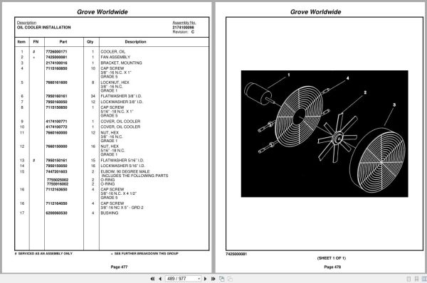
Oil Cooler Installation
Fan Assembly
Engine Installation – Cummins 6bta5.9
Valve Assembly – Solenoid
Pump Assembly
Cylinder Assembly – Throttle
Disconnect Assembly – Pump
Battery Installation
Battery Cover Installation
Electrical System Installation – Carrier
Harness Assembly – Carrier
Relay Box Assembly
Harness Assembly – Relay Box
Radiator Installation
Cleaner Installation – Air
Air Cleaner Assembly
Exhaust System Installation
Driveline Installation
Shaft Assembly – Propeller
Shaft Assembly – Drive
Driveline Assembly
Transmission Installation
Transmission Assembly
Transmission Assembly Converter Housing Group
Transmission Assembly Case And Rear Cover Group
Transmission Assembly Turbine Shaft Stator Support
Transmission Assembly Torque Converter Assembly
Transmission Assembly Auxiliary Pump Drive Parts
Transmission Assembly Charging Pump Drive Group
Transmission Assembly Forward Shaft Group
Transmission Assembly Control Valve Group
Transmission Assembly Reverse Idler Group
Transmission Assembly Reverse And Second Shaft
Transmission Assembly Low Speed Shaft Group
Transmission Assembly Forward High, Third And Fourth
Transmission Assembly Idler Shaft Group
Transmission Assembly Output Shaft Group
Transmission Assembly Charging Pump And Filter Group
Transmission Assembly Control Valve Assembly
Transmission Assembly Drive Plate Group
Transmission Assembly Pump Disconnect Assembly
Frame – Fifth Wheel
Axle Installation – Front
Axle Assembly – Front
Axle Assembly
Axle Assembly Differential Carrier Parts
Axle Assembly Housing Parts
Axle Assembly Wheel End Parts
Axle Assembly Brake Caliper
Cylinder Assembly – 3″ Steer
Chamber Assembly – Brake
Axle Assembly Brake Caliper Assembly
Axle Installation – Rear
Axle Assembly – Rear
Cylinder Assembly – 5″ Lockout
Axle Assembly Brake Caliper Parts
Rear Steer Indicator Installation
Valve Installation – Rear Axle Lockout
Hydraulic Lines Installation – Front Steer
Hydraulic Schematic – Rear Axle Lockout
Hydraulic Schematic – Brake
Hydraulic Schematic – Rear Steer
Hydraulic Lines Installation – Brake
Tire And Wheel Assembly
Outrigger Beam Installation
Cylinder Assembly – 4 1/2″ Outrigger Jack
Cylinder Assembly – Outrigger Extension
Valve Installation – Outrigger Valve
Valve Assembly – 4 Stack Outrigger Solenoid
Valve Assembly – Holding
Outrigger Float Stowage Installation
Float Assembly – Outrigger
Hydraulic Lines Installation – Outrigger
Engine Hood Installation
Relief Valve And Parking Brake Installation
Valve Assembly – Relief
Valve Assembly – Brake
Exterior Lights Installation
Mirror Installation – Frame
Fender Installation
Hydraulic Reservoir Installation
Reservoir Assembly – Hydraulic
Cover Assembly – 16’’ Inspection
Filter Assembly – Return
Valve, Sampling And Bleeding
Fuel Tank And Step Installation
Decking Installation
Back-Up Alarm Installation
Weatherstrip Installation – Engine Hood
Hook Block Tie-Down Installation

REALEASE :
REALEASE :

REALEASE :
REALEASE :

REALEASE :
REALEASE :

REALEASE :
REALEASE :

REALEASE :
REALEASE :

REALEASE :
REALEASE :

REALEASE :
REALEASE :

REALEASE :
REALEASE :
 Automotive - Heavy Equipment - Truck & Bus - Forklift - Crane