
0 ITEMSVIEW CART

✓
Expert Support
✓
Full Speed
✓
100% Working
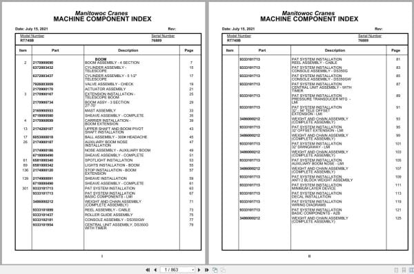
Grove Crane RT740B 76889 Parts Manual 2021
Size: 6.84 MB
Format: PDF
Language: English
Brand: Grove
Type of Machine: Crane
Type of Manual: Parts Manual
Model: Grove RT740B Crane
Serial Number: 76889
Publication Date: 2021
Number of Pages: 863 Pages
40 USD
- Description
Description
Contents:
Boom Assembly – 4 Section
Cylinder Assembly -Telescope
Cylinder Assembly – 5 1/2″Telescope
Valve Assembly – Check
Actuator Assembly
Extension Installation -Telescope Boom
Boom Assy – 3 Section27′-70′
Mast Assembly
Sheave Assembly – Complete
Carrier Installation -Boom Extension
Upper Shaft And Boom Pivotshaft Installation
Ball Assembly – 300# Headache
Auxiliary Boom Nose Installation
Nose Assembly – Auxiliary Boom
Spotlight Installation
Lights Installation – Boom
Stop Installation – Boom Extension
Sheave Installation
Pat System Installation
Pat System Installation basic Components – Lmi
Weight And Chain Assembly (Complete Assembly)
Reel Assembly – Cable
Roller Guide Assembly
Console Assembly – Ds350gw
Central Unit Assembly , Ds350gwith Timer
Pat System Installation reel Assembly – Cable
Pat System Installation console Assembly – Ds350g
Pat System Installation console Assembly – Ds350gw
Pat System Installation central Unit Assembly – With
Pat System Installation pressure Transducer Mtg –
Pat System Installation 32′ – 56′ Tele Offset
Pat System Installation 32′ Offset Extension – Lmi
Pat System Installation 32′ Swing Away – Lmi
Pat System Installation auxiliary Boom Nose – Lmi
Pat System Installation anti 2 Block Weight Assembly
Pat System Installation minimum Layer Device
Pat System Installation decal Installation
Pat System Installation wiring Diagrams
Pat System Installation basic Components – A2b
Console Assembly anti 2 Block
Pat System Installation console Assembly – A2b
Pat System Installation 32′ Offset Extension – A2b
Pat System Installation 32′ Swing Away – A2b
Pat System Installation auxiliary Boom Nose – A2b
Pat System Installation minimum Layer
Turntable Drive Installation
Swing Box Assembly -Complete
Swing Box And Brake Assembly
Brake Assembly – Swing
Motor Assembly – Orbit
Box Assembly – Swing
Brake Assembly – Swing(Complete Assembly)
Lower Shaft And Lift Cylinder Installation
Cylinder Assembly – Lift
Idler And Cable Follower Installation
Rotation Indicator Sensor Installation
Sensor Assembly – Rotation Indicator
Lock Pin Installation -Turntable
Bearing Bolt Installation
Swivel Installation -Electric And Hydraulic
Swivel Assembly -15 Port Hydraulic
Slip Ring Assembly – 44conductor
Valve Installation – Control- Main And Auxiliary
Valve Assembly – 2 Section Control
Valve Assembly -2 Section
Valve Assembly – 1 Section Control
Cartridge, Relief -1500 Psi
Cylinder Assembly – Master And Brake Booster
Valve Assembly -Pressure Reducing
Valve Assembly -Flow Control
Valve Assembly – Sequence
Valve Assembly – 5 Station Solenoid
Hydraulic Lines Installation -Telescope
Hydraulic Lines Installation -Swing
Hydraulic Lines Installation – Lift
Mirror Installation -Hoist
Flow Divider Installation
Valve Assembly – Flow Divider
Switch Installation -Auxiliary Hoist
Hydraulic Schematic -Main And Auxiliary Hoist
Hydraulic Lines Installation -Swing And Brake
Pedal And Valve Installation – Telescope
Valve Assembly – Control
Electrical System Installation
Harness Assembly -Superstructure
Electrical System – Cab
Cab Installation
Valve Assembly – Treadle
Cable Assembly – Control
Valve Assembly – Steering Control
Column Assembly – Steering
Steering Wheel Assembly
Fan Assembly – 12 Volt Cab
Fire Extinguisher Assembly
Door Assembly – Cab
Console Installation -Front
Shift Control – Threespeed
Control Handles Installation
Rotation Indicator Assembly
Mirror Installation – Cab
Pedal Installation -Swing Brake
Hydraulic Heater Installation
Blower Fan Assembly
Harness Assembly – Heater
Valve Assembly – Heater
Pump Installation – Heater
Pump Assembly – Heater
Reservoir Assembly – Power(W/O Return To Center Steering)
Control Seat Installation
Seat Assembly – Control
Seat Assembly
Valve Assembly – Joy Stick(Complete Assembly)
Mat Installation – Floor
Astray Installation – Ash
Acoustical Installation
Wiper Installation -Electric Skylight
Switch Installation – A.V.Warning
Hydraulic Lines Installation -Heater
Hydraulic Lines Installation -Heater (Cab)
Hydraulic Schematic -Testpanel
Boom Light Switch Installation
Work Light Installation
Hydraulic Lines Installation -Supply, Pressure And Return
Frame – Fifth Wheel
Axle Installation – Front
Chamber Assembly – Brake
Axle Assembly
Axle Assembly differential Carrier Parts
Axle Assembly housing Parts
Axle Assembly wheel End Parts
Axle Assembly brake Caliper Assembly
Cylinder Assembly – 3″Steer
Axle Installation – Rear
Cylinder Assembly – 5″Lockout
Axle Assembly brake Caliper Parts
Outrigger Beam Installation
Cylinder Assembly – 4 1/2″Outrigger Jack
Cylinder Assembly -Outrigger Extension
Driveline Installation
Driveline Assembly
Shaft Assembly – Drive
Engine Installation -Cummins 6bta5.9
Quick Start Installation
Valve Assembly – Solenoid
Transmission Installation
Transmission Assembly
Transmission Assembly converter Housing Group
Transmission Assembly case And Rear Cover Group
Transmission Assembly turbine Shaft Stator Support
Transmission Assembly drive Plate Assembly
Transmission Assembly torque Converter Assembly
Transmission Assembly charging Pump Group
Transmission Assembly auxiliary Pump Drive Parts
Transmission Assembly disconnect Assembly – Pump
Transmission Assembly forward Shaft Group
Transmission Assembly reverse Idler Group
Transmission Assembly reverse And Second Shaft
Transmission Assembly low Speed Shaft Group
Transmission Assembly forward High, Third And Fourth
Transmission Assembly idler Shaft Group
Transmission Assembly output Shaft Group With
Transmission Assembly charging Pump And Valve Group
Transmission Assembly control Valve Group
Control Valve Assy. Group
Alternator
Pump Assembly
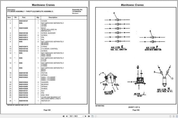
Cylinder Assembly – Throttle(Complete Assembly)
Harness Assembly – Cumminsengine
Resistor Assembly
Link Assembly – Fusible
Disconnect Assembly – Pump
Hood Installation – Engine
Mirror Installation -Frame
Relief Valve And Parking Brake Installation
Valve Assembly – Relief
Valve Assembly – Park Brake(Complete Assembly)
Exterior Lights Installation
Battery Installation
Battery Cover Installation
Electrical System Installation – Carrier
Harness Assembly – Carrier
Relay Box Assembly
Harness Assembly – Relay Box
Rear Steer Indicator Installation
Fender Installation
Hydraulic Reservoir Installation
Reservoir Assembly – Hydraulic
Filter Assembly – Return
Valve, Sampling Andbleeding
Fuel Tank And Step Installation
Radiator Installation
Cooler Installation – Oil
Fan Assembly
Decking Installation
Valve Installation -Outrigger Valve
Valve Assembly – 4 Stack Outrigger Solenoid
Valve Assembly -Holding
Tire And Wheel Assembly
Outrigger Float Stowage Installation
Float Assembly – Outrigger
Flasher Light Installation
Back-Up Alarm Installation
Valve Installation – Rear Axle Lockout
Weatherstrip Installation – Engine Hood
Hydraulic Lines Installation – Outrigger
Hydraulic Lines Installation -Front Steer
Hydraulic Schematic – Rear Axle Lockout
Hydraulic Schematic – Brake
Hydraulic Schematic – Rear Steer
Hydraulic Lines Installation -Brake
Hook Block Tie-Down Installation
Cleaner Installation – Air
Cleaner Assembly – Air
Exhaust System Installation
Belt & Filter Cumm 6bta5.9
Decal Installation -Rt700b
Related Products
-
Grove Crane 2024 Collection Parts Document 72.1 GB PDF
Original price was: 1,200.840Current price is: 840. USDThis is an offline spare parts catalog, you need to use this to sell the spare parts and it can help you a little with assembly. It’s from a manufacturer and the best in the world.Hot-30%
REALEASE :
REALEASE :
-
Grove Crane AT ATS Series Collection Parts Document PDF 447 MB
Original price was: 400.70Current price is: 70. USDIf you are a technician, You will need to use this product to repair your vehicleHot-83%
REALEASE :
REALEASE :
-
Grove Parts Document Crane GMK Series Collection 17.1 GB PDF
Original price was: 500.290Current price is: 290. USDThis is an offline spare parts catalog, you need to use this to sell the spare parts and it can help you a little with assembly. It’s from a manufacturer and the best in the world.Hot-42%
REALEASE :
REALEASE :
-
Grove GMK EPC Spare Part Catalog Manual 2023 PDF EN DE
Original price was: 600.70Current price is: 70. USDThis is an offline spare parts catalog, you need to use this to sell the spare parts and it can help you a little with assembly. It’s from a manufacturer and the best in the world.Hot-88%
REALEASE :
REALEASE :
-
Grove Crane RT GRT Series Collection Parts Document PDF 43 GB
Original price was: 500.340Current price is: 340. USDThis is an offline spare parts catalog, you need to use this to sell the spare parts and it can help you a little with assembly. It’s from a manufacturer and the best in the world.Hot-32%
REALEASE :
REALEASE :
-
Grove RT EPC Spare Parts Catalog Manual 2023 PDF EN
Original price was: 2,000.540Current price is: 540. USDThis is an offline spare parts catalog, you need to use this to sell the spare parts and it can help you a little with assembly. It’s from a manufacturer and the best in the world.Hot-73%
REALEASE :
REALEASE :
-
Grove Parts Document Crane 7.82 Gb TM TMS TT TTS Series Collection PDF
Original price was: 400.250Current price is: 250. USDThis is an offline spare parts catalog, you need to use this to sell the spare parts and it can help you a little with assembly. It’s from a manufacturer and the best in the world.Hot-38%
REALEASE :
REALEASE :
-
Grove Crane 1.8 Gb YB Series Collection Parts Document PDF
Original price was: 300.70Current price is: 70. USDThis is an offline spare parts catalog, you need to use this to sell the spare parts and it can help you a little with assembly. It’s from a manufacturer and the best in the world.Hot-77%
REALEASE :
REALEASE :