
1 ITEMVIEW CART

Total: 50.00
Expert Support
Full Speed
100% Working
15 USD
Contents:
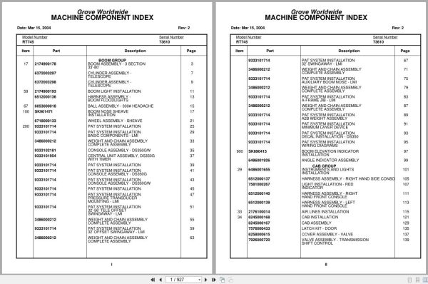
Grove Worldwide
Boom Assembly – 3 Section 33’-80’
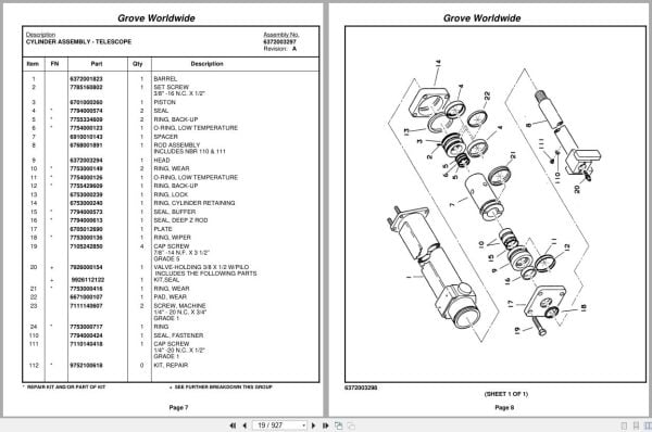
Cylinder Assembly – Telescope
Boom Light Installation
Harness Assembly – Boom Floodlights
Ball Assembly – 300# Headache
Boom Nose Sheave Installation
Wheel Assembly – Sheave
Pat System Installation
Pat System Installation Basic Components – Lmi
Weight And Chain Assembly Complete Assembly
Console Assembly – Ds350gw
Central Unit Assembly , Ds350g With Timer
Pat System Installation Console Assembly – Ds350g
Pat System Installation Console Assembly – Ds350gw
Pat System Installation Pressure Transducer
Pat System Installation 32’-56’ Tele Offset
Pat System Installation 32’ Offset Swing Away – Lmi
Pat System Installation 32’ Swing Away – Lmi
Pat System Installation Auxiliary Boom Nose – Lmi
Pat System Installation A-Frame Jib – Lmi
Pat System Installation A2b Weight Assembly
Pat System Installation Minimum Layer Device
Pat System Installation Decal Installation – Ds350
Pat System Installation Wiring Diagrams
Boom Elevation Indicator Installation
Angle Indicator Assembly
Instruments And Lights Installation
Harness Assembly – Right Hand Side Console
Light Installation – Red Indicator
Harness Assembly – Right Hand Front Console
Harness Assembly – Left Hand Front Console
Air Lines Installation
Cab Installation
Cab Assembly
Latch Kit – Door
Cover Assembly – Valve
Valve Assembly – Transmission Shift Control
Control Assembly – Steering
Valve Assembly – Selector
Pedal And Valve Assembly – Accelerator
Valve Assembly – Control
Valve Assembly – Spring Brake
Valve Assembly – Dual Brake
Control Lever Lockout Installation
Cylinder Assembly – Air
Acoustical Installation
Heater And Defroster Installation
Heater Assembly – Propane
Seat Installation
Seat Assembly
Fire Extinguisher Installation
Mirror Installation
Lines Installation – Transmission Shift
Valve And Pedal Installation – Swing Brake
Valve Assembly – Power Brake
Electrical System Installation
Harness Assembly – Superstructure
Harness Assembly – S/S Cab Interior
Fuse And Connector Panel Assembly
Harness Assembly – Connector Panel
Fan Installation – Cab Circulating
Fan Assembly – 12 Volt Cab Complete Assembly
Weatherstrip Installation – Cab
Warning System Installation – Audio/Visual
Grab Rail Installation
Load Chart Manual Installation
Panel Installation – Hydraulic Test
Control Valve And Linkage Installation
Valve Assembly – 4 Section
Valve Assembly – Outlet
Valve Section – Inlet (A-35 Series)
Valve Assembly – Relief 1000 Psi
Relief Valve
Cartridge Assembly
Valve Assembly – 1 Section
Valve Assembly – Section Outlet (A-20 Series)
Valve Bank Assembly – 3 Section (A-20 Series)
Valve Assembly – Section Inlet (A-20 Series)
Valve Assembly – Relief 2500 Psi
Valve Assembly – 2 Section
Hydraulic Lines Installation – Free Swing
Hydraulic Schematic- Lift
Hydraulic Lines Installation – Telescope Mid
Hydraulic Lines Installation – Telescope Fly
Hydraulic Lines Installation – Main Hoist
Hydraulic Lines Installation – Steer Hose
Hoist Installation – Main
Hoist Assembly – Model Ho-30b-16
Valves And Plumbing Installation – Hoist
Valve Assembly – Motor Control
Motor Assembly – Hydraulic
Brake Assembly
Cable Follower Installation
Rotation Indicator Installation – Model 30
Driver Assembly Driver Assembly
Indicator Assembly
Transmitter Assembly
Turntable Drive Installation
Box Assembly – Swing
Motor Assembly – Orbit
Brake Assembly – Swing
Valve Installation – Pressure Reducing
Valve Assembly – Pressure/ Reducing/Relieving
Pivot Shaft Installation – Boom
Cylinder Installation – Lift
Cylinder Assembly – 8 1/4″ Lift
Counterweight Installation
Swivel Installation – Electric/Hydraulic
Swivel Assembly – 11 Port Hydraulic
Swivel Assembly – 12 Port Air/Hydraulic
Ring Assembly – Slip
Reel Installation – Hose
Hose Reel Assembly – Right Hand
Bearing Bolt Installation
Manifold Installation – Hydraulic
Warning System Installation
Turntable Lock Pin Installation Installation
Lock Installation – Swing
Swing Lock Assembly
Engine Installation – Caterpillar 3208
Radiator And Oil Cooler Installation
Exhaust System Installation
Cleaner Installation – Air Not Available As Assembly
Cleaner Assembly – Air
Clutch/Lube Oil Pressure Check Point Installation
Battery Installation
Filter Assembly – Oil
Torque Converter Assembly
Pump Assembly – Steer
Cylinder Assembly – Throttle
Pump And Disconnect Installation – 4 Stage
Disconnect Assembly – Pump Not Available As Assembly
Pump Assembly
Harness Assembly – Engine
Link Assembly – Fusible
Fitting
Starter Installation Not Available As Assembly
Engine Hood Assembly &
Door Assembly
Cover And Disconnect Installation – Pump
Fuel/Water Separater Installation
Fuel/Water Separater Assembly
Quick Start Installation
Transmission Installation
Transmission Assembly
Transmission Assembly Front Cover And Case Assembly
Transmission Assembly Clutch And Gear Parts – Main
Transmission Assembly Disconnect Assembly
Transmission Assembly Reverse, Third, Forward And
Transmission Assembly Low Clutch Group
Transmission Assembly Control Valve Assembly
Cylinder Assembly – Air Lockout
Transmission And Torque Converter Installation
Driveline Installation
Driveline Assembly
Axle Installation – Front
Axle Assembly
Axle Assembly Differential Carrier Assembly
Axle Assembly Housing Assembly
Axle Assembly Brake Assembly
Axle Assembly Hub And Shaft Group
Axle Assembly Fail Safe Brake Chamber
Cylinder Assembly – Steer
Valve Installation – Front Steer
Valve Assembly – Relief
Axle Installation – Rear
Cylinder Assembly – Lockout
Valve Installation – Rear Axle Lockout
Valve Assembly
Valve Assembly Transmission
Lug Nut And Washer Installation
Rear Steer Indicator Installation
Switch Assembly – Limit
Hydraulic Lines Installation – Front Steer
Hydraulic Lines Installation – Rear Steer
Hydraulic Lines Installation – Axle Lockout
Relief Valve Installation – Rear Steer
Tire And Wheel Assembly
Outrigger Beam Installation
Cylinder Assembly – 6″ Outrigger Jack Complete Assembly
Cylinder Assembly – 2 1/2″ Outrigger Extension
Outrigger Valve Installation
Valve Assembly – Sequence
Valve Assembly – 4 Stack Outrigger Solenoid
Valve Assembly – Solenoid
Float Assembly – Outrigger
Hydraulic Lines Installation – Outrigger
Storage Installation – Front Outrigger Pad
Frame – 5th Wheel
Tank Installation – Fuel
Reservoir And Deck Installation
Front Deck Cover And Storage Well Installation
Air Lines Installation – Carrier
Dryer Assembly – Air
Cover Installation – Deck
Rear View Mirror Installation
Fender Installation
Grab Handle Installation
Lights And Turn Signals Installation
Pintle Hook Installation
Pintle Hook Assembly
Wiring Harness Assembly – Carrier Frame
Hydraulic Lines Installation – Supply, Pressure And Return
Valve Assembly – Check
Alarm Installation – Back-Up
Decal Installation – Rt700 Series

REALEASE :
REALEASE :

REALEASE :
REALEASE :

REALEASE :
REALEASE :

REALEASE :
REALEASE :

REALEASE :
REALEASE :

REALEASE :
REALEASE :

REALEASE :
REALEASE :

REALEASE :
REALEASE :
 Automotive - Heavy Equipment - Truck & Bus - Forklift - Crane