
14 ITEMSVIEW CART


Total: 630.00
Expert Support
Full Speed
100% Working
15 USD
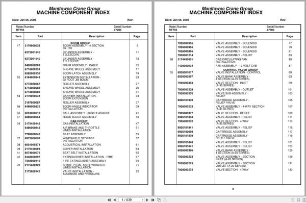
Contents:
Boom Assembly – 4 Section 35’-110’
Cylinder Assembly – Telescope
Drum Assembly – Cable
Sheave Wheel Assembly
Boom Latch Assembly
Extension Installation – 32 Foot Jib Boom
Roller Assembly
Carrier Installation – Boom Extension
Boom Angle Indicator Installation
Ball Assembly – 300# Headache
Hook Block Assembly
Cab Installation
Air Brake And Throttle Lines Installation
Seat Assembly
Windshield Storage Installation
Acoustical Installation
Cover Installation
Seat Belt Installation
Extinguisher Installation – Fire
Fire Extinguisher Assembly
Brake Pedal And Hydraulic Lines Installation
Valve Installation – Solenoid And Pressure
Valve Assembly – Solenoid
Valve Assembly – Relief
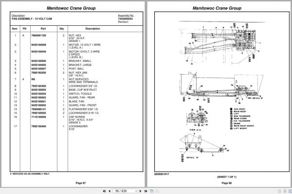
Cab Circulating Fan Installation
Fan Assembly – 12 Volt Cab
Valve Installation – Control
Valve Bank Assembly – 4 Section (A-35 Series)
Valve Section – Inlet (A-35 Series)
Valve Assembly – Outlet
Valve Sub- Assembly – Relief
Cartridge Assembly – Relief Valve
Valve Assembly – 4-Way Section (A-35 Series)
Valve Section – Relief
Valve Section – 4 Way (A-35 Series)
Cartridge Assembly
Valve Bank Assembly – 1 Section (A-20 Series)
Valve Assembly – Section Inlet (A-20 Series)
Valve Assembly – Section Outlet (A-20 Series)
Valve Section – 4 Way
Valve Assembly – Relief 1500 Psi
Valve Bank Assembly – 3 Section (A-20 Series)
Valve Assembly – Relief 2500 Psi
Valve Bank Assembly – 1 Section (A-35 Series)
Free Swing – Hydraulic Schematic
Hydraulic Lines Installation – Lift
Hydraulic Lines Installation – Telescope Mid
Hydraulic Lines Installation – Telescope Fly
Hoist Installation – Main
Hoist Assembly – Model Ho30b-16
Motor Assembly , Hydraulic
Valve Assembly – Selector
Valve Assembly – Motor Control
Follower Installation – Cable
Rotation Indicator Installation
Driver Assembly Driver Assembly
Indicator Assembly
Transmitter Assembly
Grove Hoist – Hydraulic Schematic
Turntable Drive Installation
Swing Box And Brake Assembly
Motor Assembly – Orbit
Brake Assembly
Cylinder Installation – Lift
Cylinder Assembly – Lift
Counterweight Installation
Swivel Installation – Electro – Hydraulic
Swivel Assembly – Hydraulic
Swivel Assembly – 10 Port
Ring Assembly – Slip 32 Conductor
Reel Installation – Hose
Hose Reel Assembly – Right Hand
Emergency Air Tank Installation
Elevation And Swing Warning Installation
Switch Assembly – Limit
Pin Installation – Turntable Lock
Engine Installation – Cummins V-555-C
Filter Assembly – Oil
Torque Converter Assembly
Fitting Assy
Pump Assembly – Steer
Engine Hood Assembly &
Door Assembly
Fuel/Water Separater Installation
Fuel/Water Separater Assembly
Quick Start Installation Not Available As Assembly
Shifter Installation – Hi-Lo
Cylinder Assembly – Air
Valve Assembly – 3 Way Solenoid
Transmission Installation
Transmission Assembly
Transmission Assembly Front Cover And Case Assembly
Transmission Assembly Clutch And Gear Parts – Main
Transmission Assembly Disconnect Assembly
Transmission Assembly Reverse, Third, Forward And
Transmission Assembly Low Clutch Group
Transmission Assembly Control Valve Assembly
Hydraulic Shift, Converter Line Installation
Driveline Installation
Driveline (Front Axle)
Driveline Assembly
Driveline (Rear Axle)
Driveline (Transmission)
Axle Installation – Front
Axle Assembly
Axle Assembly Differential Carrier Assembly
Axle Assembly Housing Assembly
Axle Assembly Brake Assembly
Axle Assembly Hub And Shaft Group
Axle Assembly Fail Safe Brake Chamber
Cylinder Assembly – Steer
Valve Installation – Front Steer
Axle Installation – Rear
Cylinder Assembly -Lockout
Axle Assembly – Rear Drive Steer
Valve Installation – Rear Axle Lockout
Tire And Wheel Assembly
Lug Nut And Washer Installation
Rear Steer Indicator Installation
Front Steer – Hydraulic Schematic
Rear Steer – Hydraulic Schematic
Axle Lockout – Hydraulic Schematic
Outrigger Installation – Front & Rear
Cylinder Assembly – Stabilizer
Cylinder Assembly – Extension
Valve Assembly – Sequence
Valve Assembly – 4 Stack Outrigger Solenoid
Float Assembly – Outrigger
Hydraulic Lines Installation – Outrigger
Cover And Handle Assembly – Hydraulic Pump Disconnect
Fuel Tank, Battery Box,And Cover Installation
Reservoir And Deck Installation
Air Tanks, Valves, And Cover Installation
Valve Assembly – Quick Release
Valve Assembly – Relay
Air Brake And Throttle Line Installation
Valve Assembly – Check
Rear View Mirror Installation
Fender Installation
Lights And Turn Signals Installation
Electrical System Installation (Carrier)
Hydraulic Lines Installation – Supply, Pressure And Return
Decal Installation – Rt740/755
Wiring Diagram

REALEASE :
REALEASE :

REALEASE :
REALEASE :

REALEASE :
REALEASE :

REALEASE :
REALEASE :

REALEASE :
REALEASE :

REALEASE :
REALEASE :

REALEASE :
REALEASE :

REALEASE :
REALEASE :
 Automotive - Heavy Equipment - Truck & Bus - Forklift - Crane