
0 ITEMSVIEW CART


✓
Expert Support
✓
Full Speed
✓
100% Working
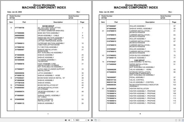
Grove Crane RT75S 32729 Parts Manual 2004
Size: 5.28 MB
Format: PDF
Language: English
Brand: Grove
Type of Machine: Crane
Type of Manual: Parts Manual
Model: Grove RT75S Crane
Serial Number: 32729
Publication Date: 2004
Number of Pages: 663 Pages
15 USD
- Description
Description
Contents:
35’- 110’ 4 Section Lattice Trapezoidal Boom
Base Section Assembly
Drum Assembly – Cable
Inner-Mid Section Assembly Complete 3 And 4 Section
Outer-Mid Section Assembly 4 Section Lattice Boom
Fly Section Assembly
Sheave Installation – Boom Nose
Sheave Assembly
Cylinder Assembly – Telescope
Foot Assembly And Installation , Cylinder
Latch And Cylinder Support Installation
Latch Assembly
Sheave Assembly – Hose
Boom Nose Sheave Install. 15″
Sheave Wheel
Boom Installation Kit
Jib Boom Installation – 24’ A-Frame
Jib Boom Assembly – 24’ A-Frame
Sheave Wheel Assembly 3/4’’ Cable
Boom Extension Installation – 32’
Roller Assembly
Sheave Wheel Assembly
Carrier Installation – Boom Extension
Hook Block Assembly
Cab Assembly & Install.
Wiper Installation – Windshield
Valve Assembly – Horn
Storage Installation – Removable Windshield
Pedal Assembly
Valve, Control
Valve Assembly – Control
Boom Pointer/Angle Indicator Assembly
Heater Installation
Heater Assembly – Propane
Lock Installation – Window Not Available As Assembly
Control Installation – Modified Main And Auxiliary
Valve Bank Assembly – 3 Section (A-35 Series)
Valve Section – Inlet (A-35 Series)
Valve Assembly – Outlet
Valve Assembly – 4-Way Section (A-35 Series)
Valve Section – Relief
Valve Assembly – Relief
Valve Section – 4 Way (A-35 Series)
Cartridge Assembly
Valve Bank Assembly – 3 Section (A-20 Series)
Valve Assembly – Section Inlet (A-20 Series)
Valve Assembly – Relief 2500 Psi
Valve Assembly – Section Outlet (A-20 Series)
Valve Section – 4 Way
Valve Bank Assembly – Two Section A-35 Series
Lines-Supply,Press& Return Hyd
Lift – Hydraulic Schematic
Grove Model 30 Main And Model 15 Auxiliary Hoist
Telescope Mid-Hyd Schematic
Telescope Fly (Hydraulic Schematic)
Lines Install – Swing Hyd.
Valve Bank Assembly – 1 Section (A-20 Series)
Valve Assembly – Relief 1500 Psi
Follower Installation – Cable
Rotation Ind.Install.
Main Hoist Install. Mod.30
Hoist Assembly
Group Assembly – Left Hand Not Available As Assembly
Group Assembly – Right Hand Not Available As Assembly
Motor Assembly – Hydraulic
Valve Assembly – Selector
Hoist Installation
Gear Reduction Assembly
Lift Cylinder Installation
Cylinder Assembly – Lift
Counter-Weight Installation
Hose Reel Installation
Reel Assembly – Hose
Emergency Air Tank Install.
Elevation And Swing Warning Installation
Switch Assembly – Limit
Turntable Weldment And Drive Assembly
Box Assembly – Swing
Box Assembly – Swing Model 200
Swing Box Assembly – Model 200
Brake Assembly – Disc
Brake Assembly – Mechanical
Motor Assembly – Orbit
Boom Pivot Bearing Parts
Swivel Assy With Cat Eng
Swivel Assembly – Hydraulic
Swivel Assembly – 10 Port
Ring Assembly – Slip
Hyd.Pump & Disc.Handle Install
Cover And Handle Assembly – Hydraulic Pump Disconnect
Engine Installation ( Cat. )
Radiator And Oil Cooler Installation
Hood Assembly – Engine
Exhaust System Installation
Cleaner Installation – Air Not Available As Assembly
Cleaner Assembly – Air
Quick Start Installation Not Available As Assembly
Clutch/Lube Oil Pressure Check Point Installation
Filter Assembly – Oil
Filter Assembly – Primary Fuel
Transmission Installation
Transmission Assembly
Valve Assembly – Transmission Shift Control
Transmission Assembly Valve Assembly –
Driveline Assembly
Front Driveline Installation
Rear Axle & Range Shifter
Rear Axle And Range Shift Assembly
Cylinder Assembly – Air
Valve Assembly – 3-Way Solenoid
Hyd.Trans&Torq.Conv.Lines Inst
Front Axle Installation
Axle Assembly
Axle Assembly Axle
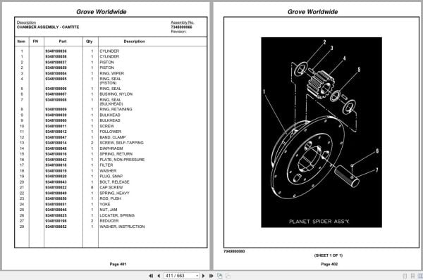
Chamber Assembly – Camtite
Axle Assembly Planet Spider Assembly
Axle Assembly Tie Rod Assembly
Axle Assembly Differential And Carrier
Axle Assembly Air Brake Assembly
Cylinder Assembly – 4″ Steer Complete Assembly
Rear Axle Installation
Axle Assembly – Rear Drive Steer
Cylinder Assembly – 6.00’’ Lockout
Cylinder Assembly – 3″ Steer Complete Assembly
Tire And Wheel Assembly
Valve Installation – Rear Axle Lockout
Valve Installation – Front Steer
Lines Install-Front Steer Hyd
Lines Install – Rear Steer Hyd
Axle Lockout – Hydraulic Schematic
Outrigger Installation Hyd.
Hydraulic Outrigger Assembly
Cylinder Assembly – Stabilizer
Cylinder Assembly – 3″ Outrigger
Float Assembly – Outrigger Aluminum
Valve Install.Front & Rear O/R
Valve Assembly – 4 Stack Outrigger Solenoid
Lines Install – Outrigger Hyd
Valve, Pressure Relief
Hyd.Tank & Decking Install.
Deck And Hydraulic Tank Assembly
Tank Installation – Fuel
Terminal Block Assembly
Light And Turn Signal Installation
Fenders And Storage Well Assembly And Installation
Air Brake And Throttle Lines (Use With Cat Engine Only)
Valve Assembly – Check
Wiring Diagram Schematic
Related Products
-
Grove Crane 2024 Collection Parts Document 72.1 GB PDF
Original price was: 1,200.840Current price is: 840. USDThis is an offline spare parts catalog, you need to use this to sell the spare parts and it can help you a little with assembly. It’s from a manufacturer and the best in the world.Hot-30%
REALEASE :
REALEASE :
-
Grove Crane 1.8 Gb YB Series Collection Parts Document PDF
Original price was: 300.70Current price is: 70. USDThis is an offline spare parts catalog, you need to use this to sell the spare parts and it can help you a little with assembly. It’s from a manufacturer and the best in the world.Hot-77%
REALEASE :
REALEASE :
-
Grove GMK EPC Spare Part Catalog Manual 2023 PDF EN DE
Original price was: 600.70Current price is: 70. USDThis is an offline spare parts catalog, you need to use this to sell the spare parts and it can help you a little with assembly. It’s from a manufacturer and the best in the world.Hot-88%
REALEASE :
REALEASE :
-
Grove Crane AT ATS Series Collection Parts Document PDF 447 MB
Original price was: 400.70Current price is: 70. USDIf you are a technician, You will need to use this product to repair your vehicleHot-83%
REALEASE :
REALEASE :
-
Grove Parts Document Crane GMK Series Collection 17.1 GB PDF
Original price was: 500.290Current price is: 290. USDThis is an offline spare parts catalog, you need to use this to sell the spare parts and it can help you a little with assembly. It’s from a manufacturer and the best in the world.Hot-42%
REALEASE :
REALEASE :
-
Grove Parts Document Crane 7.82 Gb TM TMS TT TTS Series Collection PDF
Original price was: 400.250Current price is: 250. USDThis is an offline spare parts catalog, you need to use this to sell the spare parts and it can help you a little with assembly. It’s from a manufacturer and the best in the world.Hot-38%
REALEASE :
REALEASE :
-
Grove Crane RT GRT Series Collection Parts Document PDF 43 GB
Original price was: 500.340Current price is: 340. USDThis is an offline spare parts catalog, you need to use this to sell the spare parts and it can help you a little with assembly. It’s from a manufacturer and the best in the world.Hot-32%
REALEASE :
REALEASE :
-
Grove RT EPC Spare Parts Catalog Manual 2023 PDF EN
Original price was: 2,000.540Current price is: 540. USDThis is an offline spare parts catalog, you need to use this to sell the spare parts and it can help you a little with assembly. It’s from a manufacturer and the best in the world.Hot-73%
REALEASE :
REALEASE :