
1 ITEMVIEW CART
Total: 10.00
Expert Support
Full Speed
100% Working
30 USD
Contents:
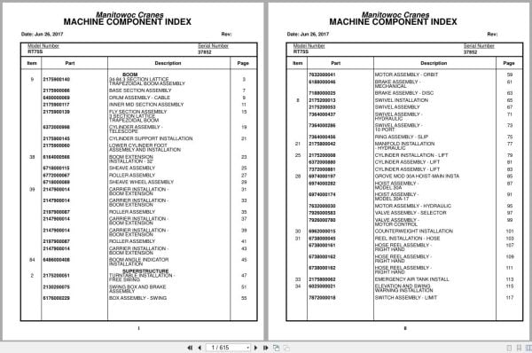
34-84 3 Section Lattice Trapezoidal Boom Assembly
Base Section Assembly
Drum Assembly – Cable
Inner Mid Section Assembly
Fly Section Assembly 3 Section Lattice
Cylinder Assembly – Telescope
Cylinder Support Installation
Boom Extension Installation – 32′
Sheave Assembly
Roller Assembly
Sheave Wheel Assembly
Carrier Installation – Boom Extension
Boom Angle Indicator Installation
Turntable Installation – Free Swing
Swing Box And Brake Assembly
Box Assembly – Swing
Motor Assembly – Orbit
Brake Assembly – Mechanical
Brake Assembly – Disc
Swivel Installation
Swivel Assembly
Swivel Assembly – Hydraulic
Swivel Assembly – 10 Port
Ring Assembly – Slip
Manifold Installation – Hydraulic
Cylinder Installation – Lift
Cylinder Assembly – Lift
Grove Mod 30a Hoist-Main Insta
Hoist Assembly – Model 30a
Hoist Assembly – Model 30a-17
Motor Assembly – Hydraulic
Valve Assembly – Selector
Valve Assembly – Motor Control
Counterweight Installation
Reel Installation – Hose
Hose Reel Assembly – Right Hand
Emergency Air Tank Install
Elevation And Swing Warning Installation
Switch Assembly – Limit
Follower Installation – Cable
Rotation Indicator Inst. Main
Rotation Indicator Assembly -Hoist Drum
Supply,Press.& Return Hyd.Sch
Lift – Hydraulic Schematic
Hydraulic Lines Install – Fly Telescope Schematic
Grove Model 30a Main Hoist – (Hydraulic Schematic)
Tube Support Installation – Grove Model 30 Main
Pin Installation – Turntable Lock
Pivot Shaft Installation – Boom
Bearing Bolt Installation
Hydraulic Shift Converter Line Installation
Cab Assembly And Installation
Cab Sub Assembly
Door Assembly
Control Handle Assembly – (Main)
Control Handle Assembly – (Auxiliary)
Control Handle Assembly – (Lift)
Control Handle Assembly (Rear Steering)
Control Handle Assembly – (Mid)
Handle, Control
Handle Control
Controls Installation (Not Available As Assembly )
Pedal Assembly
Valve, Control
Valve Assembly – Control
Valve Assembly – Transmission Shift Control
Valve Assembly
Valve Assembly – Steering
Valve Assembly – Horn
Windshield Wiper Installation
Instruments And Lights Installation
R.H. Side Console Assembly (Front)
R.H. Side Console Assembly – Front
Console Panel Assembly
Panel – Right Hand Side Front
Lock Installation – Window (Not Available As Assembly )
Acoustical Installation
Hydraulic Lines Installation
Cable Installation – Parking Brake
Cable Assembly – Brake
Axle Installation – Front
Cylinder Assembly – Steer
Rear Axle Installation
Cylinder Assembly -Lockout
Axle Assembly – Rear
Axle Assembly – Drive/Steer
3″ Steer Cylinder Assy
Hyd. Outrigger Install.
Cylinder Assembly – Stabilizer
Cylinder Assembly – Outrigger
Outrigger Assembly
Float Assembly – Outrigger
Valve Assembly – Relief
Valve Assembly – 4 Stack Outrigger Solenoid
Valve Assembly – Outrigger Selector (Complete Assembly )
Transmission Installation
Transmission Assembly
Trans. Assy. Case Group
Trans. Clutch & Gear Group
Trans. Low Clutch Group
Trans. Rev.3rd & 2nd Clutch Gr
Trans. Disconnect Group
Trans. Valve Assy. Group
Cummins V-555-C Engine Installation
Cummins V-555-C Engine Assembly
Converter Assembly – Torque
Pump Assembly – Steer
Throttle Installation – Cummins V-555-C
Cylinder Assembly – Throttle
Pump And Disconnect Installation – 4 Stage
Disconnect Assembly – Pump (Not Available As Assembly )
Pump Assembly
Radiator And Oil Cooler Installation
Cleaner Installation – Air
Cleaner Assembly – Air
Exhaust System Installation
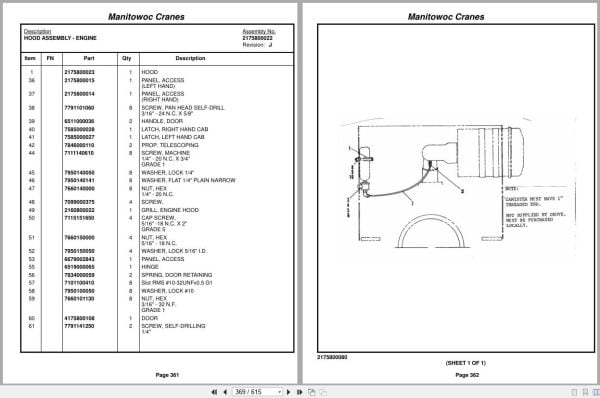
Hood Assembly – Engine
Quick Start Installation (Not Available As Assembly )
Wiring Diagram – Hourmeter
Filter Assembly – Oil
Clutch/Lube Oil Pressure Check Point Installation
Driveline Installation
Driveline (Front Axle)
Driveline Assembly
Driveline (Rear Axle)
Driveline (Transmission)
Hydraulic Reservoir And Deck Installation
Hydraulic Reservoir And Deck Assembly
Fuel Tank,Batt.Box &Cover Inst
Air Tanks, Valves, And Cover Installation
Valve Assembly – Quick Release
Valve Assembly – Relay
Valve Install.Front & Rear O/R
Shifter Installation – Hi-Lo
Cylinder Assembly – Air
Valve Assembly – 3 Way Solenoid
Front Deck Cover And Storage Well Installation
Valve Installation – Rear Axle Lockout
Valve Installation – Front Steer
Transmission And Converter Lines Installation
Light And Turn Signal Installation
Fenders And Storage Well Assembly And Installation
Rear Axle Lockout Override Installation
Valve Assembly – Solenoid
Indicator Installation – Rear Steer
Hydraulic Lines Installation – Outrigger
Valve, Pressure Relief
Front Steering – (Hydraulic Schematic)
Hydraulic Lines Installation – Rear Steer
Hydraulic Lines Installation – Axle Lockout With Override
Rear View Mirror Installation
Alarm Installation – Back-Up
Air Brake And Throttle Line Installation
Valve Assembly – Check
Air Brake And Throttle Lines Installation
Decal Installation – Rt65s/75s

REALEASE :
REALEASE :

REALEASE :
REALEASE :

REALEASE :
REALEASE :

REALEASE :
REALEASE :

REALEASE :
REALEASE :

REALEASE :
REALEASE :

REALEASE :
REALEASE :

REALEASE :
REALEASE :
 Automotive - Heavy Equipment - Truck & Bus - Forklift - Crane