
0 ITEMSVIEW CART


✓
Expert Support
✓
Full Speed
✓
100% Working
Grove Crane RT760E 223896 Parts Manual 2004
Size: 9.85 MB
Format: PDF
Language: English
Brand: Grove
Type of Machine: Crane
Type of Manual: Parts Manual
Model: Grove RT760E Crane
Serial Number: 223896
Publication Date: 2004
Number of Pages: 907 Pages
15 USD
- Description
Description
Contents:
Boom Assy (110 Ft Long)
Cylinder Assembly – 6″ Telescope Complete Assembly
Cylinder Assembly – 6.00’’ Telescopic
Boom Pivot Shaft Installation Upper Boom
Weight And Chain Assembly Complete Assembly
Sheave Install – 2 Over 4
Sheave Assembly
Kit,Wear Pad
Folding Offset Bm Ext Install
Folding Offset Bm Ext Assy
Bm Ext Fly Assy
Sheave Assembly – Complete
Mast Assembly
Bm Ext Align Install
Ext Carr Install (W/Stinger)
Hook Block Assembly – 60 Ton Quick Reeve
Overhaul Ball Assembly Complete Assembly
Kit Installation – Iflex 5 Lmi Boom
Cable Reel Lwg508 – Iflex 5
Box Assembly – Junction
Flag Assembly – A2b Retainer
Connector Assembly Dummy Plug, 2-Pin
Socket, 3/4’’ Open Wedge
Load Moment Indicator Kit
Boom Extension Kit
Junction Box Assembly – 80mm X 75mm, Pg9 + 2-Pin
Lmi Boom Install Kit – Iflex 5
Kit Installation – Auxiliary Boom Nose
Nose Installation – Auxiliary Boom
Extension Installation – Boom
Stop Block Install
Cab Installation
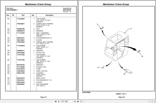
Cab Assembly
Cab Section
Skylight Assembly – Sliding
Window Assembly – Rear Complete Assembly
Cable Assembly
Fan Assembly – 12 Volt Cab Complete Assembly
Ctrl Seat Install S.A. W/Aux
Ctrl Seat Assy S.A. W/Aux
Switch Assembly – Proximity
Controller Assembly – Single Axis
Harness Assy Seat Rt700e2
Acoustics Install – Rt”E”
Rt”E” Series Acoustics Kit
Console Installation – Front
Console Assembly – Front
Panel Assembly – Front Console
Harness Assy-Front Console
Ha-Potentiometer
Electrical System Installation – Cab
Lever Installation – 360 Degree
Tele Pedal Install.
Valve Assembly – Control
Screen Installation – Sun
Lmi Internal Light Bar Kit
Pedal Installation – Brake
Valve Assembly – Brake With Treadle
Lmi S/S – Iflex 5
Shifter Installation – Transmission
Kit Installation – Iflex 5 Lmi Superstructure
Rod Installation – Lock Pin
Valve Installation – Steer
Valve Assembly – Steering Control
Air Cond Install – S/S
Kit – Hydraulic Air Conditioner Unit 12 Volt
Hyd. Motor Assembly
Pedal Installation – Throttle (Electric)
Esi-S/S Rt700e
Harness Assy S/S
Lmi Cab Kit – Iflex 5
Centeral Unit – Iflex 5
Graph. Console (Ver.) – Iflex5
Kit Installation – Iflex5 Lmi Cab
Switch Installation – Air Conditioner
A/C Lines Install – Cab
Kit – Air Conditioner Hose Complete Assembly
Cover Installation – Cab Rear
Tele Pedal Linkage Install
Valve Installation – Control (Without Counterweight Removal)
Directional Control Valve
Valve Assembly – Pressure Reducing With Solenoid
Valve Assembly – Directional Control Complete Assembly
Hydraulic Lines Installation – Supply, Pressure And Return
Valve Assembly – Residual Check
Lift Hyd Lines Install-S/S
Main & Aux Hoist Hyd Lines Ins
Tele Hyd Lines Install-S/S
Valve Assembly – Sequence
Swing Hyd Lines Install-S/S
Lmi Hyd Lines Install-S/S
S, P & R Hyd Lines Install-Cab
Tele W/Aux H. Hyd Lines Install
Swing & Sw. Brake Hyd Lines In
M. & Aux Hoist Hyd Lines Install
Lift Hyd Lines Install-Cab
Steer Hyd Lines Install-Cab
Brake Hyd Lines Install-Cab
Ho30g-16g Main And Aux Hoist Installation
Ho30g-16g Hoist Assembly (12 Volt Dc)
Ho30g-16g Hoist Assembly Complete Assembly
Group Assembly – Right Hand
Group Assembly – Left Hand
Center Group – Hoist
Motor Assembly – Hydraulic Vane Type Complete Assembly
Brake Assembly
Vlvs & Plmbg (12vdc)
Valve Assembly – Counterweight Complete Assembly
30g-16g Flwr & Idlr
Kicker Installation
Indicator Installation – Hoist Rotation
Control Assembly – Central Processing Unit
Mirror Installation – Hoist
Lock Installation – Swing
Swing Lock Assembly
Cwt Install
Swivel Installation – Electric, Water And Hydraulic
Swivel Assembly – Electric, Water And Hydraulic
Swivel Assembly – 10 Port Hydraulic Complete Assembly
Swivel Assembly – 2 Port Water Complete Assembly
Ring Assembly – Slip 15 Conductor
Bearing Bolt Installation
Cover Installation – Valve
Cylinder Installation – Lift
Cylinder Assembly – 12″
Valve Assembly – Holding Complete Assembly
Hood Installation – Engine
Engine Installation – Cummins Qsb
Engine Assembly – Cummins Qsb Not Available As Assembly
Transmission
Housing,Converter Group
Case,Transmission Group
Rear Cover Group
Drive Plate Group
Turb.Shaft/Oil Baffle Group
Turbine/Impeller Group
Pump Drive Group
Rev.High Shaft Group
Fwd.& 2nd. Shaft Group
Low Shaft Group
Idler Shaft Group
Output Shaft Group
Reg.Valve/Charge Pump Group
Elect.Control Valve Group
Hi & Low Shift Control Group
Pump Adaptor Group
Pump Assembly – Two Section Piggyback
Pump Ass’y – P330
Filter Assembly Complete Assembly
Electrical System Installation – Engine
Harness Assembly – Engine Complete Assembly
Cable Kit-Rt700e2 Engine
Radiator Installation
Radiator Assembly Not Available As Assembly
Radiator/Cac
Exhaust System Installation
Air Cleaner Install
Cleaner Assembly – Air Complete Assembly
Driveline Install
Coupling Shaft
Shaft Assembly – Rear Slip Complete Assembly
Front Lower Slip Shaft
Rear Axle L/O Hyd Lines Install
Serv Brake Hyd Lines-Disc
Rear Steer Hyd Lines Install-Car
Frt Steer Hyd Lines Install-Carr
Axle Disc & Park Brake Lines
Switch Assembly – Pressure (Normally Closed)
Valve Assembly – Solenoid (4 Wheel Drive)
Axle Installation – Rear Standard Differential
Axle Assembly – Rear Drive Steer Without Differential Lock
Diff.Carrier Group @ 5.86:1
Housing Group
Hub & Shaft Group
Brake Group
Brake Assembly Group
Cylinder Assembly – 3 1/2″ Steer Complete Assembly
Cylinder Assembly – 5″ Lockout Complete Assembly
Front Axle Installation – Standard Differential
Axle Assembly – Front Drive Steer Without Differential Lock
Brake Assembly – Parking Complete Assembly
Tire And Wheel Installation – 29.5 X 25 General
Tire And Wheel Assembly – 29.5 X 25 General
Tie Down Installation – Hook Block
Cover Installation – Outrigger Grill And
O/R Hyd Lines-Carr
Carrier Frame Complete
Frame Assembly
Beam Installation – Outrigger Not Available As Assembly
Beam Assembly – Outrigger
Cylinder Assembly – 4 1/2″ Jack Complete Assembly
Cylinder Assembly – Outrigger Extend
Cylinder Assembly – 2 1/2″ O/R Extension Complete Assembly
Decal Install Rt700e2-Std
Decal Installation – Rt700e2 (Standard)
Decal Install Rt700e2-Std-Carr
Decal Install Rt700e2-Std-S/S
Decal Install Rt700e2-Std-Boom
Decal Install Rt700e-Nomencltr
Fender Install W/Storage Tray Ma
Full Decking Install
Outrigger Float Stowage Install.
Float Assembly – Outrigger
Rt700e2 Decal
Exterior Lights & Alarm Install
Mirror Installation – Rear View
Hardware Kit – Decal
Extension Installation – Step
Hydraulic Tank & Steps Installation
Tank Assembly – Hydraulic
Filter Assembly – Return
Hyd Vlve Inst-Carrier W/O Diff
Manifold Assembly – Outrigger Control
Valve Assembly – Selector Outrigger And Rear Steer
Valve Assembly – Double Solenoid
Valve Assembly – 4-Way Solenoid
Valve Assembly – Solenoid
Valve-Hi Speed Boost
Fuel Tank & Step Install
Tank Assembly – Fuel
Battery Installation
Cable Kit-Rt700e Batteries
Protector Installation – Fender
Related Products
-
Grove Crane 2024 Collection Parts Document 72.1 GB PDF
Original price was: 1,200.840Current price is: 840. USDThis is an offline spare parts catalog, you need to use this to sell the spare parts and it can help you a little with assembly. It’s from a manufacturer and the best in the world.Hot-30%
REALEASE :
REALEASE :
-
Grove Crane 1.8 Gb YB Series Collection Parts Document PDF
Original price was: 300.70Current price is: 70. USDThis is an offline spare parts catalog, you need to use this to sell the spare parts and it can help you a little with assembly. It’s from a manufacturer and the best in the world.Hot-77%
REALEASE :
REALEASE :
-
Grove Parts Document Crane GMK Series Collection 17.1 GB PDF
Original price was: 500.290Current price is: 290. USDThis is an offline spare parts catalog, you need to use this to sell the spare parts and it can help you a little with assembly. It’s from a manufacturer and the best in the world.Hot-42%
REALEASE :
REALEASE :
-
Grove GMK EPC Spare Part Catalog Manual 2023 PDF EN DE
Original price was: 600.70Current price is: 70. USDThis is an offline spare parts catalog, you need to use this to sell the spare parts and it can help you a little with assembly. It’s from a manufacturer and the best in the world.Hot-88%
REALEASE :
REALEASE :
-
Grove Parts Document Crane 7.82 Gb TM TMS TT TTS Series Collection PDF
Original price was: 400.250Current price is: 250. USDThis is an offline spare parts catalog, you need to use this to sell the spare parts and it can help you a little with assembly. It’s from a manufacturer and the best in the world.Hot-38%
REALEASE :
REALEASE :
-
Grove RT EPC Spare Parts Catalog Manual 2023 PDF EN
Original price was: 2,000.540Current price is: 540. USDThis is an offline spare parts catalog, you need to use this to sell the spare parts and it can help you a little with assembly. It’s from a manufacturer and the best in the world.Hot-73%
REALEASE :
REALEASE :
-
Grove Crane AT ATS Series Collection Parts Document PDF 447 MB
Original price was: 400.70Current price is: 70. USDIf you are a technician, You will need to use this product to repair your vehicleHot-83%
REALEASE :
REALEASE :
-
Grove Crane RT GRT Series Collection Parts Document PDF 43 GB
Original price was: 500.340Current price is: 340. USDThis is an offline spare parts catalog, you need to use this to sell the spare parts and it can help you a little with assembly. It’s from a manufacturer and the best in the world.Hot-32%
REALEASE :
REALEASE :