
11 ITEMSVIEW CART


Total: 1,215.00
Expert Support
Full Speed
100% Working
20 USD
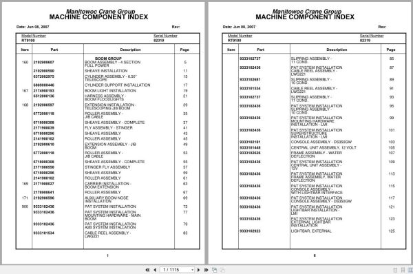
Contents:
Boom Assembly – 4 Section Full Power
Sheave Installation
Cylinder Assembly – 6.50’’ Telescope
Cylinder Support Installation
Boom Light Installation
Harness Assembly – Boom Floodlights
Extension Installation – Telescoping Jib Boom
Roller Assembly – Jib Cable
Sheave Assembly – Complete
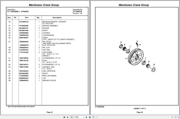
Fly Assembly – Stinger
Sheave Assembly
Roller Assembly
Extension Assembly – Jib Boom
Stinger Fly Assembly
Carrier Installation – Boom Extension
Auxiliary Boom Nose Installation
Pat System Installation
Pat System Installation Mounting Hardware – Main
Pat System Installation A2b System Installation
Cable Reel Assembly – Lwg221
Slip Ring Assembly – 11 Cond.
Pat System Installation Cable Reel Assembly –
Slip Ring Assembly – 10 Cond.
Pat System Installation Slip Ring Assembly –
Pat System Installation Mounting Hardware
Pat System Installation Superstructure
Console Assembly – Ds350gw
Central Unit Assembly , 12 Volt
Frame Assembly – Water Deflection
Pat System Installation Central Unit Assembly –
Pat System Installation Frame Assembly , Water
Pat System Installation Console Assembly –
Pat System Installation Console Assembly – Ds350gw
Pat System Installation Light Bar Installation –
Pat System Installation External Light Bar
Light Bar, External
Light Bar Driver Assembly (External)
Pat System Installation Light Bar –
Pat System Installation Light Bar Driver Assembly
Pat System Installation Transducer Installation –
Pat System Installation 3rd Wrap Limit
Device Assembly , Third Wrap (Special)
Control Unit Assembly , Mwd 100 – Third Wrap
Pat System Installation Control Unit Assembly –
Pat System Installation 3rd Wrap Device – Special
Pat System Installation Auxiliary Boom Nose
Pat System Installation Offset S/A Extension
Pat System Installation Tele-Extension
Pat System Installation 88’ Fixed Lattice Jib
Pat System Installation Jumper Cable Assembly
Pat System Installation Weight Assembly – A2b
Pat System Installation Decal – Lmi
A/V Warning System Installation
Light Installation – Red Indicator
Controls Installation – Pump Disconnect
Harness Assembly – Remote Crank
Air Lines Installation
Cab Installation
Cab Section
Console Assembly
Latch Kit – Door
Cover Assembly – Valve
Valve Assembly – Transmission Shift Control
Valve Assembly – Steering Control
Shaft Assembly – Pivot
Lockout Installation – Automatic Control Lever
Cylinder Assembly – Air
Valve Assembly – Selector
Pedal And Valve Assembly – Accelerator
Valve Assembly – Control
Valve Assembly – Spring Brake
Valve Assembly – Dual Brake
Instruments And Lights Installation (Cummins)
Right Hand Side Console Assembly –
Harness Assembly – Console
Panel Assembly – Front Console
Harness Assembly – Right Hand Front Console
Harness Assembly – Engine
Valve And Pedal Installation – Swing Brake
Valve Assembly – Power Brake
Weatherstrip Installation – Cab
Seat Installation
Seat Assembly
Fan Installation – Cab Circulating
Fan Assembly – 12 Volt Cab Complete Assembly
Acoustical Installation
Grab Rail Installation
Front Steer – Hydraulic Schematic
Heater And Defroster Installation
Heater Assembly – Propane
Heater Assembly – Propane Circuit Board Assembly
Heater Assembly – Propane Fuel And Ignition Systems
Heater Assembly – Propane Remote Control Parts
Heater Assembly – Propane Control Panel Parts
Heater Assembly – Propane Motor And Blower Parts
Heater Assembly – Propane Case And Exchanger Parts
Heater Assembly – Propane Regulator And Exhaust Parts
Extinguisher Installation – Fire
Skylight Wiper Installation
Spotlight Installation
Rotating Light Installation
Load Chart Manual Installation
Lines Installation – Transmission Shift
Panel Installation – Hydraulic Test
Valve Installation – Pressure Reducing
Valve Assembly – Pressure/ Reducing/Relieving
Hydraulic Lines Installation
Control Valve And Linkage Installation
Valve Assembly – 4 Section
Valve Assembly – Outlet
Valve Assembly – 2 Section Control
Valve Assembly – 1 Section Control
Hydraulic Lines Installation – Free Swing
Hydraulic Lines Installation – Inner Mid Telescope
Hydraulic Lines Installation – Fly Telescope
Hoist Installation – Main And Auxiliary
Hoist Assembly
Motor Assembly – Hydraulic
Brake Assembly
Valves And Plumbing Installation
Valve Assembly – Motor Control
Cable Follower And Idler Drum Assembly
Hydraulic Lines Installation – Hoist
Indicator Installation – Ho30b Hoist Rotation
Bearing Bolt Installation
Manifold Installation – Hydraulic Suction
Valve Assembly – Dry
Dry Valve Assembly
Turntable Drive Installation
Box Assembly – Swing
Swing Box And Brake Assembly
Brake Assembly – Swing
Motor Assembly – Orbit
Lock Assembly – Swing
Lock Installation – Swing
Control Lever Installation
Counterweight Installation
Swivel Installation – Electric, Air And Hydraulic
Swivel Assembly – 14 Port Hydraulic
Swivel Assembly – 12 Port Air/Hydraulic
Slip Ring Assembly – 36 Conductor
Elevation And Swing Warning Installation
Hydraulic Oil Cooler And By-Pass Valve Installation
Motor Assembly – Fan
Fan Assembly – Oil Cooler
Cooler Assembly – Oil
Hose Reel Installation
Reel Assembly – Hose
Electrical System Installation – S/S
Harness Assembly – Superstructure
Harness Assembly – S/S Cab Interior
Fuse And Connector Assembly
Harness Assembly – Fuse And Connector Panel
Cylinder Installation – Lift
Cylinder Assembly – Lift
Valve Assembly – Overcenter
Hydraulic Lines Installation – Lift
Lock Pin Installation – Turntable
Shaft Installation – Boom Pivot
Electrical System Installation
Harness Assembly – Carrier
Alarm Installation – Back-Up
Engine Installation – For Reference Only
Engine Assembly – Cummins 6cta8.3
Torque Converter Installation
Torque Converter, Clark C270
Pressure Reg. Valve Group
Converter Housing Group
Wheel & Impeller Group
Drive Plate Group
Stator Support Group
Output & Turbine Shaft Group
Charge Pump Group
Charge Pump Assy. Group
Pump Drive Shaft Group
Pump Drive Group
Pump Adaptor Group
Pump Assembly
Cylinder Assembly – Throttle
Compressor Assembly – Air
Harness Assembly – Cummins Engine
Pump Assembly – Piggyback
Pump Assembly – Steer
Disconnect Assembly – Pump
Valve Assembly – Shuttle
Engine Components – Cummins 6cta8.3
Radiator Installation
Muffler Installation
Cleaner Installation – Air
Cleaner Assembly – Air Complete Assembly
Quick Start Installation
Hood Installation – Engine
Door Assembly – Left Hand
Door Assembly – Right Hand
Weatherstrip Installation – Engine Hood
Battery Installation
Counterweight Installation – Engine
Transmission Installation
Transmission Assembly
Transmission Assembly Flange Group
Transmission Assembly Remote Case Group
Transmission Assembly Case And Rear Cover Group
Transmission Assembly Reverse And High Shaft Group
Transmission Assembly Forward And Second Shaft
Transmission Assembly Low Speed Shaft Group
Transmission Assembly Idler Shaft Group
Transmission Assembly Output Shaft Group
Transmission Assembly Control Valve Assembly
Transmission Assembly High And Low Range Shift
Shifter Installation – Range Rear Axle
Range Shifter Assembly – Rear Axle
Cylinder Assembly – Air Lockout
Valve Assembly Transmission
Driveline Installation
Driveline Assembly
Front Axle Installation
Axle Assembly – Drive Steer
Cylinder Assembly – 4″ Steer
Hydraulic Lines Installation – Front Steer
Front Steer Relief Valve Installation
Valve Assembly – Relief
Axle Installation – Rear
Cylinder Assembly – 7″ Lockout
Rear Steer Indicator Installation
Valve Installation – Rear Axle Lockout
Valve Assembly – Rear Axle Lockout
Tire And Wheel Assembly
Wheel And Disc Assembly
Tire Inflation Kit Installation
Tire Inflation Kit
Valve Assembly – Check
Outrigger Control Valve Installation
Valve Assembly – 4 Stack Outrigger Solenoid
Valve Assembly – Integrated Outrigger
(Carrier) Hydraulic Lines Installation – Outrigger
Outrigger Pad And Storage Installation
Float Assembly – Outrigger Complete Assembly
Beam Installation – Outrigger
Cylinder Assembly – 6.00’’ Outrigger Jack
Cylinder Assembly – 2 1/2″ Outrigger Extension
Dryer Assembly – Air
Hydraulic Reservoir Installation
Filter Assembly – Oil
Cover, Hydraulic Tank Installation
Tank Installation – Fuel
Tank Assembly – Fuel 100 Gallon
Tool Box And Ladder Installation
Turn Signal And Clearance Lights Installation
Rear View Mirror Installation
Pintle Hook Installation
Hook Assembly – Pintle
Filter Installation – Oil Converter
Pump Cover Installation
Decal Installation – Rt9100
Sk950664
Fenders And Battery Box Installation
Rear Steer – Hydraulic Schematic
Hydraulic Schematic – Axle Lockout

REALEASE :
REALEASE :

REALEASE :
REALEASE :

REALEASE :
REALEASE :

REALEASE :
REALEASE :

REALEASE :
REALEASE :

REALEASE :
REALEASE :

REALEASE :
REALEASE :

REALEASE :
REALEASE :
 Automotive - Heavy Equipment - Truck & Bus - Forklift - Crane