
1 ITEMVIEW CART

Total: 100.00
Expert Support
Full Speed
100% Working
40 USD
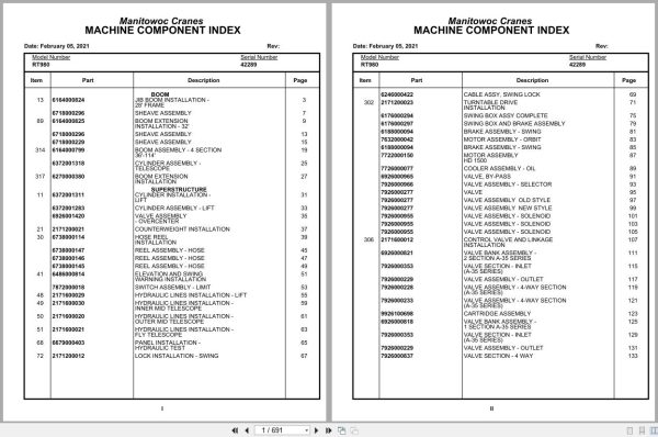
Contents:
Jib Boom Installation -28′ Frame
Sheave Assembly
Boom Extension Installation – 32′
Boom Assembly – 4 Section36′-114′
Cylinder Assembly -Telescope
Boom Extension Installation
Cylinder Installation -Lift
Cylinder Assembly – Lift
Valve Assembly – Overcenter
Counterweight Installation
Hose Reel Installation
Reel Assembly – Hose
Elevation And Swing Warning Installation
Switch Assembly – Limit
Hydraulic Lines Installation – Lift
Hydraulic Lines Installation -Inner Mid Telescope
Hydraulic Lines Installation -Outer Mid Telescope
Hydraulic Lines Installation -Fly Telescope
Panel Installation -Hydraulic Test
Lock Installation – Swing
Cable Assy, Swing Lock
Turntable Drive Installation
Swing Box Assy Complete
Swing Box And Brake Assembly
Brake Assembly – Swing
Motor Assembly – Orbit
Motor Assembly hd 1500
Cooler Assembly – Oil
Valve, By-Pass
Valve Assembly – Selector
Valve
Valve Assembly Old Style
Valve Assembly New Style
Valve Assembly – Solenoid
Control Valve And Linkage Installation
Valve Bank Assembly -2 Section A-35 Series
Valve Section – Inlet(A-35 Series)
Valve Assembly – Outlet
Valve Assembly – 4-Way Section(A-35 Series)
Cartridge Assembly
Valve Bank Assembly -1 Section A-35 Series
Valve Section – 4 Way
Relief Valve
Valve Section – Relief
Valve Assembly – Relief
Valve Bank Assembly -1 Section A-20 Series
Valve Assembly – Section Inlet (A-20 Series)
Valve Section – Outlet
Valve Bank Assembly -4 Section A-35 Series
Hydraulic Lines Installation -Main And Auxiliary
Free Swing – Hydraulic Schematic
Hoist Installation – Main
Hoist Assembly -Model Ho30a-26
Motor Assembly , Hydraulic
Valve Assembly -Motor Control
Idler Drum Assembly -Cable(Boom Clearance)
Hoist Installation -Auxiliary
Idler Drum Assembly
Roller Assembly – Cable
Hoist Assembly -Model Ho30b-16
Swivel Installation -Electro/Hydraulic
Swivel Assembly -Air/Hydraulic
Ring Assembly – Slip36 Conductor
Rotation Indicator Installation
Driver Assembly driver Assembly
Indicator Assembly
Transmitter Assembly
Electrical Systems Installation
Brake Pedal Hydraulic Lines Installation
Front Steer – Hydraulic Schematic
Instruments And Lights Installation
Heater/Defroster And Fuel Tank Installation
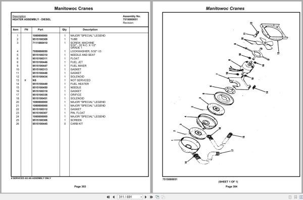
Heater Assembly – Diesel
Cab Assembly
Control Assembly -(W/O Return To Center Steering)
Controls Installation
Valve Assembly – Transmission Shift Control
Pedal And Valve Assembly -Accelerator
Valve Assembly – Control
Valve Assembly -Spring Brake
Valve Assembly – Dual Brake
Lines Install – S/S Air(Not Available As Assembly)
Transmission Shifthydraulic Schematic
Acoustical Installation
Axle Installation -Front
Axle Assembly
Axle Assembly housing Assembly
Axle Assembly differential Carrier Assembly
Axle Assembly hub And Shaft Group
Axle Assembly brake Assembly
Axle Assembly air Chamber Assembly
Axle Assembly air Chamber Parts
Cylinder Assembly – Steer
Engine Installation -Gmc 6-71t
Torque Converter Assembly
Torque Converter Assy. Group
Press. Reg.& Charge Pump Group
Pump Disconnect Assy. Group
Pump Assembly – 3 Section
Pump Assembly – Steering
Cylinder Assembly – Throttle
Driveline Installation
Propeller Shaft
Driveline Assembly
Reservoir Installation -Hydraulic
Filter Assembly – Oil
Tire And Wheel Assembly
Cover, Hydraulic Tank Installation
Tool Box And Ladder Installation
Tank Installation – Fuel
Hood Installation – Engine
Door Assembly -Left Hand
Door Assembly -Right Hand
Battery Installation
Pump Disconnect Controls Installation
Hydraulic Lines Installation -Outrigger
Hydraulic Lines Installation -Front Steer
Rear Steer – Hydraulic Schematic
Axle Lockout – Hydraulic Schematic
Transmission And Converterhydraulic Schematic
Return Lines Manifold Installation
Front Steer Relief Valve Installation
Filter Installation – Oilconverter
Air Lines Installation –
Dryer Assembly – Air
Valve, Relay
Fenders And Battery Box Installation
Lights And Back-Up Alarm Installation
Hydraulic Lines Installation -Supply, Pressure And Return
Valve Assembly – Sequence
Rear Axle Lockout Override Installation
Rear Axle Lockout Valve Installation
Electrical System Installation -Carrier Frame
Transmission Assembly And Installation
Transmission Assembly
Transmission Assembly main Housing And Output Shaft
Transmission Assembly clutch And Gear Parts – Main
Transmission Assembly reverse And Third, Forward
Transmission Assembly low Clutch Group
Transmission Assembly disconnect Assembly
Valve Assembly transmission
Cylinder Assembly – Air Lockout
Beam Installation -Outrigger
Cylinder Assembly -Stabilizer
Cylinder Assembly -Extension
Valve Assembly – 4 Stack Outrigger Solenoid
Valve Assembly – Outrigger Selector(Complete Assembly)
Float Assembly – Outrigger(Complete Assembly)
Decal Installation -Rt980

REALEASE :
REALEASE :

REALEASE :
REALEASE :

REALEASE :
REALEASE :

REALEASE :
REALEASE :

REALEASE :
REALEASE :

REALEASE :
REALEASE :

REALEASE :
REALEASE :

REALEASE :
REALEASE :
 Automotive - Heavy Equipment - Truck & Bus - Forklift - Crane