
9 ITEMSVIEW CART


Total: 300.00
Expert Support
Full Speed
100% Working
20 USD
Contents:
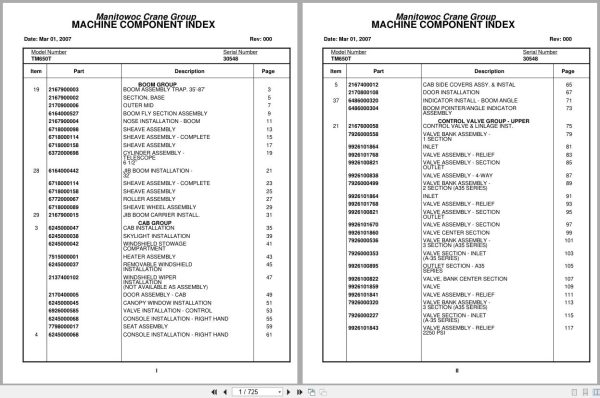
Boom Group
Boom Assembly Trap. 35’-87’
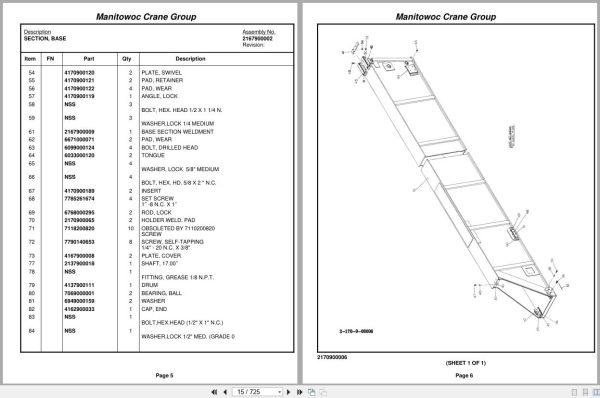
Section, Base
Outer Mid
Boom Fly Section Assembly
Nose Installation – Boom
Sheave Assembly
Sheave Assembly – Complete
Sheave Assembly
Cylinder Assembly –
Telescope
6 1/2’’
Jib Boom Installation –
32’
Sheave Assembly – Complete
Sheave Assembly
Roller Assembly
Sheave Wheel Assembly
Jib Boom Carrier Install.
Cab Group
Cab Installation
Skylight Installation
Windshield Stowage
Compartment
Heater Assembly
Removable Windshield
Installation
Windshield Wiper
Installation
(Not Available As Assembly)
Door Assembly – Cab
Canopy Window Installation
Valve Installation – Control
Console Installation – Right Hand
Seat Assembly
Console Installation – Right Hand
Cab Side Covers Assy. & Instal
Door Installation
Indicator Install – Boom Angle
Boom Pointer/Angle Indicator
Assembly
Control Valve Group – Upper
Control Valve & Linlage Inst.
Valve Bank Assembly –
1 Section
Inlet
Valve Assembly – Relief
Valve Assembly – Section
Outlet
Valve Assembly – 4-Way
Valve Bank Assembly –
2 Section (A35 Series)
Inlet
Valve Assembly – Relief
Valve Assembly – Section
Outlet
Valve Assembly – Section
Valve Center Section
Valve Bank Assembly –
3 Section (A35 Series)
Valve Section – Inlet
(A-35 Series)
Outlet Section – A35
Series
Valve, Bank Center Section
Valve
Valve Assembly – Relief
Valve Bank Assembly –
3 Section (A35 Series)
Valve Section – Inlet
(A-35 Series)
Valve Assembly – Relief
2250 Psi
Cartridge Assembly
Section, Outlet
Valve, Bank Center Section
Valve
Valve Assembly – Relief
Valve Center Section
Cylinder Relief Valve
Cartridge Assembly
Cylinder Relief Valve
Cartridge Assembly
Valve Assembly – Outrigger Selector
Complete Assembly
Valve Installation –
A-20 Series
Valve Bank Assembly –
2 Section A-20 Series
Valve Assembly – Section
Inlet (A-20 Series)
Valve Assembly – Section
Outlet (A-20 Series)
Valve Section – 4 Way
Valve, Relief – 1250 Psi
Lift, Hyd. Schematic
Swing, Hyd. Schematic
Tele. Fly, Hyd. Schematic
Mod.30 & Mod.15 Hyd.Schematic
Swing, Hyd. Schematic
Hoist Group
Main Hoist Installation
Hoist Assembly –
Model 30a-17
Hoist Assembly –
Model 30a-17
Motor Assembly – Hydraulic
Valve Assembly – Selector
Valve Assembly – Control
Cylinder Assembly –
Hydraulic
Rotation Ind.Install.
Turntable Group
Turntable Assy.& Drive Install
Turntable Section
Hoist Mounting Structure
Box Assembly – Swing
Motor Assembly – Orbit
Swing Brake Installation
Brake Assembly – Disc
Brake Assembly – Disc
Counterweight Carrier
Installation
Cylinder Assembly –
Counterweight Mover
Counterweight Carrier
Installation
Cylinder Assembly –
Counterweight Mover
Tank Installation – Fuel
Fuel Level Sending Unit
Installation
Reservoir Assembly And
Installation – Hydraulic
Suction Manifold Installation
Valve Assembly –
Manifold Suction
Swivel Install – Elect.& Hyd.
Swivel Assembly
Collector Ring Assembly
Counterweight Installation
Valve Assembly – Cam
Hose Reel Assembly –
Right Hand
Bearing Bolt Install.
Swing Horn Install.
Hydraulic Lines Installation –
Mid Tele & Counterweight
Hydraulic Filter Install.
Lift Cylinder Install. 11″ Dia
Cylinder Assembly – Lift
Valve Assembly
– Overcenter
Engine Group
Alcohol Evaporator
Installation
Evaporator Assembly
Valve Assembly – Check
Engine Side Covers Assy.& Inst
Door Installation
Engine Side Door
Installation
Engine Install. Cummins
Pump Assembly
Exhaust And Air Cleaner
Installation
Cleaner, Air
Wiring Diagram
Wiring Diagram – Hourmeter
Drive Train Group
Drive Line Installation
Drive Line Assembly
Drive Line Assembly
Drive Line Assembly
Inter-Axle Shaft Assembly
Front Axle & Steering Install.
Suspension Assembly –
Front
Link Assembly – Drag
Link Assembly – Drag
Link Assembly – Drag
Drag Link And Steering
Valve Assembly
Cylinder Assembly – Steer
Gear Assembly – Steering
Outrigger Group
Hydraulic Outrigger Instal
Cylinder Assembly – 7″
Stabilizer
Cylinder Assembly –
Outrigger
Outrigger Remote Control Box
Frame Group
Exterior Lights And Horn
Installation
Carrier Assembly, Grove
Bd 50-60 Rear Bogie Assembly &
Installation
(Not Available As Assembly)
Beam Assembly – Equalizer
Chamber Assy,Camtite
Safety
Cab And Sheet Metal
Hood Assembly – Engine
Controls Installation
Cylinder Assembly – Master
Steering Column Assembly
Complete Assembly
Valve Assembly – Brake Pedal
Complete Assembly
Throttle Installation
(Cummins Ntc 335 )
(Not Available As Assembly)
Door Assembly
Clutch And Slave Cyl Hyd
Lines Installation
(Not Available As Assembly)
Heater And Defrosting Fan
Installation
(Not Available As Assembly)
Heater Assembly
Hydraulic Outrigger Instal
Cylinder Assembly – 7″
Stabilizer
Cylinder Assembly –
Outrigger
Front Fenders & Battery
Box Installation
Battery Box Assembly And
Installation
Rear Fender Installation
Drive Line Installation
Drive Line Assembly
Drive Line Assembly
Drive Line Assembly
Inter-Axle Shaft Assembly
Instruments And Lights
Installation
Valve Assembly – Control
Exterior Lights And Horn
Installation
Diagram, Wiring
Wiper Installation –
Windshield
(Not Available As Assembly)
Hydraulic Lines Installation –
Outrigger
Valve, Pressure Relief
Power Steering Schematic
(Cummins Ntc 335)
Air System Schematic
-8
X 4 Carrier
Valve Assembly – Check
Air Lines Installation
Air Tank Installation
Valve Assembly – Check
Valve, Quick Release
Valve Assembly – Relay
Alcohol Evaporator
Installation
Evaporator Assembly
Valve Assembly – Check
Outrigger Remote Control Box
Level Assembly
Air Brake & Elec Disconnec
(Not Shown)
Air System Schematic
– Used W/Training Boom Only
(Not Shown)
Wiring Diagram – Not Shown
(Used W/Trailing Boom Only)
Cab Carrier Group
Cab And Sheet Metal
Hood Assembly – Engine
Controls Installation
Cylinder Assembly – Master
Steering Column Assembly
Complete Assembly
Valve Assembly – Brake Pedal
Complete Assembly
Throttle Installation
(Cummins Ntc 335 )
(Not Available As Assembly)
Door Assembly
Clutch And Slave Cyl Hyd
Lines Installation
(Not Available As Assembly)
Engine Carrier Group
Engine & Transmission Install.
Transmission Assembly
Quick Start Installation
Clutch And Slave Cylinder
Installation
Clutch Assembly
Cylinder Assembly – Slave
Clutch Release Assembly
Exhaust System And Air
Cleaner Installation
Cleaner Assembly – Air
Radiator & Shutter Inst.
Radiator Shutter Kit
Assembly
Transmission Shift
Installation
Controller Assembly –
Slave Unit
Control Assembly –
Master Unit
Battery Installation
(Not Available As Assembly)
Wiring Diagram
Cleaner Installation – Air
Cleaner Assembly – Air
Complete Assembly
Valve Assembly – Control
Schematic
Wiring Diagram

REALEASE :
REALEASE :

REALEASE :
REALEASE :

REALEASE :
REALEASE :

REALEASE :
REALEASE :

REALEASE :
REALEASE :

REALEASE :
REALEASE :

REALEASE :
REALEASE :

REALEASE :
REALEASE :
 Automotive - Heavy Equipment - Truck & Bus - Forklift - Crane