
9 ITEMSVIEW CART


Total: 350.00
Expert Support
Full Speed
100% Working
15 USD
Contents:
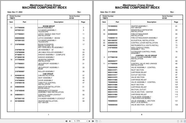
Boom Group
Boom Assembly
Cylinder Assembly –
Telescope
Latch, Saddle And Foot
Installation
Latch Assembly – Boom
Cylinder Assembly –
Telescope
Boom Extension
Installation – 32’
Not Available As Assembly
Jib Assembly – 32’
Jib Cable Roller Assembly
Sheave Assembly – Complete
Sheave Assembly
Jib Boom Carrier
Installation
Jib Support Assembly –
Front
Jib Support Assembly –
Rear
Roller Assembly
Cab Group
Cab Installation
Seat Assembly
Door Assembly
Throttle Control
Installation
Indicator Installation –
Boom Angle
Windshield Stowage
Assembly And Installation
Control Lever Lockout
Installation
Cylinder Assembly-Lockout
Heater Installation –
Hot Water
Heater Assembly –
Hot Water
Windshield Defroster
Installation
Fire Extinguisher
Installation
Fire Extinguisher Assembly
Acoustical Installation
Control Lever Installation
Instruments & Lights Install
Side Console Panel
Assembly – R.H.
Outrigger Control Panel
Assembly
Control Valve Group
Valve Cover Assembly And
Installation
Prop
Control Valve And Linkage
Installation
Valve Assembly – Control
Inlet Section
Cartirige,Relief
Outlet Section
Valve Section
Cartirige,Relief
Valve Assembly – Control
Inlet Section
Cartirige,Relief
Section, Outlet
Valve,Section – Center
Cartirige,Relief
Valve Bank Assembly –
1 Section A-20 Series
Valve Assembly – Section
Inlet (A-20 Series)
Valve Section – Outlet
Valve Section – 4 Way
Valve Assembly – Relief
1500 Psi
Valve Assembly – Relief
1500 Psi
Valve Assembly – 2 Section
Valve Section – Inlet
(A-35 Series)
Valve Assembly – Relief
2250 Psi
Cartridge Assembly
Valve Section – Outlet
Valve Assembly – 4-Way Section
(A-35 Series)
Valve Section – 4 Way
Relief Valve
Valve Assembly – Relief
2250 Psi
Cartridge Assembly
Cartridge Assembly
Relief Valve
Valve Assembly – 2 Section
Valve Section – Inlet
(A-35 Series)
Valve Assembly – Relief
2250 Psi
Cartridge Assembly
Valve Assembly – Outlet
Valve Assembly – 4-Way Section
(A-35 Series)
Valve Section – 4 Way
Relief Valve
Valve Assembly – Relief
2250 Psi
Cartridge Assembly
Cartridge Assembly
Relief Valve
Valve Assembly – Selector
Valve Assembly – Solenoid
Valve Assembly – Sequence
Valve Assembly –
Pressure Reducing
Valve Bank Assembly –
2 Section A-20 Series
Valve Assembly – Section
Inlet (A-20 Series)
Valve Assembly – Section
Outlet (A-20 Series)
Valve Section – 4 Way
Valve, Relief – 1250 Psi
Hydraulic Lines Installation –
Supply, Pressure And Return
Valve, Pressure Relief
Hydraulic Lines Installation – Swing
Hydraulic Lines Installation –
Mid And Counterweight
Hydraulic Lines Installation –
Outer Mid
Hydraulic Lines Installation – Lift
Hydraulic Lines Installation –
Main And Auxiliary Hoist
Hoist Group
Hoist Installation – Main
Cylinder Assembly –
Hydraulic
Hoist Assembly –
Model Ho30a-26
Motor Assembly, Hydraulic
Valve Assembly – Selector
Valve Assembly –
Motor Control
Valve Assembly –
Motor Control
Auxiliary Hoist
Installation
Hoist Assembly –
Model Ho15b-16
Valve Assembly – Motor
Control
Gear Reduction Assembly
Motor Assembly – Hydraulic
Idler Drum Assembly
Roller Assembly – Cable
Rotation Indicator
Installation – Model 30
Driver Assembly
Driver Assembly
Indicator Assembly
Transmitter Assembly
Rotation Indicator
Installation – Model 15
Driver Assembly
Driver Assembly
Indicator Assembly
Transmitter Assembly
Turntable Group
Drive Installation – Turntable And
Swing Box And Brake
Box Assembly – Swing
Motor Assembly – Orbit
Brake Assembly –
Mechanical
Brake Assembly – Disc
Fuel Tank Assembly And
Installation
Tank Assembly – Fuel
Fuel Level Sending Unit
Installation
Hydraulic Reservoir
Assembly And Installation
Filter Assembly
Cylinder Installation –
Lift
Cylinder Assembly – Lift
Valve Assembly
– Overcenter
Swivel Assembly –
Electric/Hydraulic
Swivel Assembly
Collector Ring Assembly
Counterweight Installation
Valve Assembly – Cam
Reel Installation – Hose
Reel Assembly – Hose
Reel Assembly – Hose
Bearing Bolt Installation
Lock Installation – Swing
Swing Horn Installation
Boom Pivot Shaft
Installation
Engine Group
Hood Installation – Engine
Prop
Prop
Engine Install – Cummins V555
Manifold Assembly
Pump Assembly
Pump, Hyd
Pump Assembly
3 Pump Drive Assembly
Fitting Assy
Cover Installation –
Cummins Engine Only
Drive Train Group
Drive Line Installation
Drive Line Assembly
Drive Line Assembly
Drive Line Assembly
Axle Group
Front Axle And Steering
Installation
Gear Assembly – Steering
Drag Link And Steering
Valve Assembly
Link Assembly – Drag
Link Assembly – Drag
Link, Drag
Axle Assembly –
Front-Front
Cylinder Assembly – Steer
Arm Assembly – Torque
Axle Assembly – Rear Front
Cylinder Assembly – Steer
Torque Arm Assembly
Equalizer Assembly
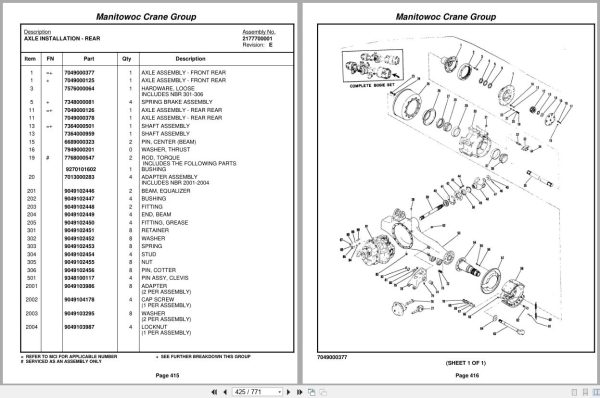
Axle Installation – Rear
Axle Assembly – Front Rear
Axle Assembly – Front Rear
Axle Assembly – Front Rear
Differential Carrier Assembly
Axle Assembly – Front Rear
Brake Assembly
Axle Assembly – Front Rear
Planet Spider Assembly
Spring Brake Assembly
Axle Assembly – Rear Rear
Axle Assembly – Rear Rear
Axle Assembly – Rear Rear
Differential And Carrier
Assembly
Axle Assembly – Rear Rear
Brake Assembly
Axle Assembly – Rear Rear
Planet Carrier Assembly
Shaft Assembly
Tire And Wheel Assembly
Back-Up Alarm Installation
Valve Extension And Spacer
Installation
Outrigger Group
Outrigger Beam
Installation
Beam Assembly – Outrigger
Cylinder Assembly –
Stabilizer
Cylinder Assembly –
Extension
Hydraulic Lines Installation – Outrigger
Valve Installation – Control
– Outrigger
Valve Assembly – 4 Stack
Outrigger Solenoid
Control Box Installation –
Outrigger
Outrigger Control Panel
Assembly
Level Installation
Level Assembly
Float Assembly – Outrigger
Frame Group
Fenders And Battery Box
Installation – Front
Fender Installation – Rear
Fuel Tank Installation
Lights And Horn
Installation – Exterior
Terminal Block Assembly – Electrical
Power Steering Schematic
Air System Lines Installation
Valve Assembly – Check
Air Tank & Valve Install
Valve, Relay
Valve Assembly –
Spring Brake
Valve Assembly – Check
Reservoir Installation –
Power Steering
Reservoir Assembly –
Power Steering
Injector Installation -Alcohol
Alcohol Injector Assembly
Mud Guard Installation
Sling Box Installation
Terminal Block Assembly – Electrical
Panel Installation – Sound
Decal Installation –
Tm875
Cab Carrier Group
Cab Installation
Cab
Door Assembly
Door Assembly
Heater Assembly –
Hot Water
Panel Installation
Washer Installation –
Windshield
Mirror Installation –
Rear View
Mirror Head And Loop
Assembly – Stainless Steel
Wiper Installation –
Windshield
Not Available As Assembly
Acoustical Installation
Engine Carrier Group
Engine And Transmission Installation
Cummins Ntc 350
Valve Assembly – Control
Pump Assembly –
Power Steering
Controller Assembly –
Slave Unit
Clutch And Slave Cyl Hyd
Lines Installation
Not Available As Assembly
Quick Start Installation
Hood Installation – Engine
Schematic
Wiring Diagram – Hourmeter

REALEASE :
REALEASE :

REALEASE :
REALEASE :

REALEASE :
REALEASE :

REALEASE :
REALEASE :

REALEASE :
REALEASE :

REALEASE :
REALEASE :

REALEASE :
REALEASE :

REALEASE :
REALEASE :
 Automotive - Heavy Equipment - Truck & Bus - Forklift - Crane