
10 ITEMSVIEW CART


Total: 315.00
Expert Support
Full Speed
100% Working
30 USD
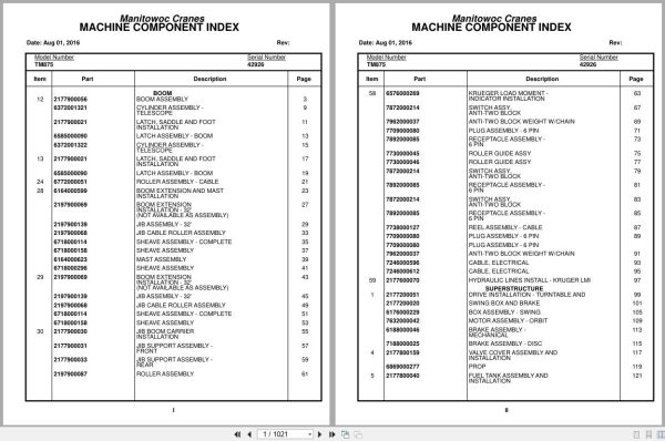
Contents:
Boom
Boom Assembly
Cylinder Assembly –
Telescope
Latch, Saddle And Foot
Installation
Latch Assembly – Boom
Cylinder Assembly –
Telescope
Latch, Saddle And Foot
Installation
Latch Assembly – Boom
Roller Assembly – Cable
Boom Extension And Mast
Installation
Boom Extension
Installation – 32′
(Not Available As Assembly)
Jib Assembly – 32′
Jib Cable Roller Assembly
Sheave Assembly – Complete
Sheave Assembly
Mast Assembly
Sheave Assembly
Boom Extension
Installation – 32′
(Not Available As Assembly)
Jib Assembly – 32′
Jib Cable Roller Assembly
Sheave Assembly – Complete
Sheave Assembly
Jib Boom Carrier
Installation
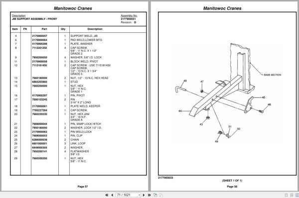
Jib Support Assembly –
Front
Jib Support Assembly –
Rear
Roller Assembly
Krueger Load Moment –
Indicator Installation
Switch Assy,
Anti-Two Block
Anti-Two Block Weight W/Chain
Plug Assembly – 6 Pin
Receptacle Assembly –
6 Pin
Roller Guide Assy
Roller Guide Assy
Switch Assy,
Anti-Two Block
Receptacle Assembly –
6 Pin
Switch Assy,
Anti-Two Block
Receptacle Assembly –
6 Pin
Reel Assembly – Cable
Plug Assembly – 6 Pin
Plug Assembly – 6 Pin
Anti-Two Block Weight W/Chain
Cable, Electrical
Cable, Electrical
Hydraulic Lines Install – Kruger Lmi
Superstructure
Drive Installation – Turntable And
Swing Box And Brake
Box Assembly – Swing
Motor Assembly – Orbit
Brake Assembly –
Mechanical
Brake Assembly – Disc
Valve Cover Assembly And
Installation
Prop
Fuel Tank Assembly And
Installation
Tank Assembly – Fuel
Fuel Level Sending Unit
Installation
Fuel Level Sending Unit
Installation
Hydraulic Reservoir
Assembly And Installation
Filter Assembly
Cylinder Installation – Lift
Cylinder Assembly – Lift
Cylinder Assembly – Lift
Valve Assembly
– Overcenter
Swivel Assembly –
Electric/Hydraulic
Swivel Assembly
Collector Ring Assembly
Control Valve And Linkage
Installation
Valve Assembly – Control
Outlet Section
Cartirige,Relief
Valve Assembly – Control
Inlet Section
Cartirige,Relief
Section, Outlet
Cartirige,Relief
Valve Bank Assembly –
1 Section A-20 Series
Valve Assembly – Section
Inlet (A-20 Series)
Valve Section – Outlet
Valve Section – 4 Way
Valve Assembly – Relief
1500 Psi
Valve Assembly – Relief
1500 Psi
Valve Assembly – 2 Section
Valve Section – Inlet
(A-35 Series)
Valve Assembly – Relief
2250 Psi
Cartridge Assembly
Valve Section – Outlet
Valve Assembly – 4-Way Section
(A-35 Series)
Valve Section – 4 Way
Relief Valve
Valve Assembly – Relief
2250 Psi
Cartridge Assembly
Cartridge Assembly
Relief Valve
Valve Assembly – 2 Section
Valve Section – Inlet
(A-35 Series)
Valve Assembly – Relief
2250 Psi
Cartridge Assembly
Valve Assembly – Outlet
Valve Assembly – 4-Way Section
(A-35 Series)
Valve Section – 4 Way
Relief Valve
Valve Assembly – Relief
2250 Psi
Cartridge Assembly
Cartridge Assembly
Relief Valve
Valve Assembly – Outrigger Selector
(Complete Assembly)
Valve Assembly – Solenoid
Valve Assembly – Sequence
Valve Assembly –
Pressure Reducing
Valve Bank Assembly –
2 Section A-20 Series
Valve Assembly – Section
Inlet (A-20 Series)
Valve Assembly – Section
Outlet (A-20 Series)
Valve Section – 4 Way
Valve, Relief – 1250 Psi
Hoist Installation
Cylinder Assembly –
Hydraulic
Hoist Assembly –
Model Ho30a-26
Motor Assembly, Hydraulic
Valve Assembly – Selector
Valve Assembly –
Motor Control
Valve Assembly –
Motor Control
Auxiliary Hoist
Installation
Hoist Assembly –
Model Ho15b-16
Valve Assembly – Motor
Control
Gear Reduction Assembly
Motor Assembly – Hydraulic
Idler Drum Assembly
Roller Assembly – Cable
Tubing Installation – Hoist
(Not Available As Assembly)
Valve Assembly –
Motor Control
Counterweight Installation
Valve Assembly – Cam
Counterweight Carrier
Installation
Cylinder Assembly –
Counterweight Mover
Reel Installation – Hose
Reel Assembly – Hose
Reel Assembly – Hose
Rotation Indicator
Installation – Model 30
Driver Assembly
Driver Assembly
Indicator Assembly
Transmitter Assembly
Rotation Indicator
Installation – Model 15
Driver Assembly
Driver Assembly
Indicator Assembly
Transmitter Assembly
Bearing Bolt Installation
Supply,Press.& Return Hyd. Sch
Valve, Pressure Relief
Hydraulic Lines Installation – Swing
Hydraulic Lines Installation –
Mid And Counterweight
Hydraulic Lines Installation –
Outer Mid
Hydraulic Lines Installation – Lift
Hydraulic Lines Installation –
Main And Auxiliary Hoist
Lock Installation – Swing
Control Lever Installation
Cable Assembly
Cable Assembly
Swing Horn Installation
Boom Pivot Shaft
Installation
Superstructure Cab
Cab Installation
Seat Assembly
Door Assembly
Controls Installation –
Swing Brake
(Not Available As Assembly)
Cylinder Assembly
Cable Assembly – Brake
Throttle Control
Installation
Indicator Installation –
Boom Angle
Windshield Stowage
Assembly And Installation
Control Lever Lockout
Installation
Cylinder Assembly-Lockout
Valve And Relay
Installation
Valve Assembly – Solenoid
Heater Installation –
Hot Water
Heater Assembly –
Hot Water
Windshield Defroster
Installation
Extinguisher Installation – Fire
Acoustical Installation
Control Lever Installation
Instruments And Lights
Installation
Lowerworks/Carrier
Hood Installation – Engine
Prop
Prop
Engine Installation –
Cummins V-555-C
Manifold Assembly
Pump Assembly
Pump Assembly – Hydraulic Gear
Pump Assembly – Hydraulic Gear
Pump Assembly
Drive Assembly – Pump
Fitting Assy
Pump Drive Remote
Disconnect Installation
Exhaust And Air Cleaner
Installation
Cleaner Assembly – Air
Clutch Installation
Clutch Assembly
Terminal Block Assembly – Electrical
Cover Installation –
Cummins Engine Only
Decal Installation –
Tm875
Engine Install – Cummins 350
Exhaust And Air Cleaner
Installation
Cleaner Assembly – Air
Radiator Installation
Transmission Shift
Installation
Control Assembly – Master
Battery Installation
Wiring Diagram
Throttle Pedal
Installation
(Not Available As Assembly)
Transmission Assembly
Clutch And Slave Cylinder
Installation
Clutch Assembly
Cylinder Assembly – Slave
Clutch Release Assembly
Valve Assembly – Control
Pump Assembly –
Power Steering
Control Assembly –
Controller Assembly –
Slave Unit
Exhaust And Air Cleaner
Installation
Cleaner Assembly – Air
Radiator Installation
Transmission Shift
Installation
Control Assembly – Master
Battery Installation
Throttle Pedal
Installation
(Not Available As Assembly)
Front Axle And Steering
Assembly And Installation
Gear Assembly – Steering
Drag Link And Steering
Valve Assembly
Link, Drag
Cylinder Assembly – Steer
Torque Arm Assembly
Cylinder Assembly – Steer
Torque Arm Assembly
Cylinder Assembly – Steer
Arm Assembly – Torque
Equalizer Assembly
Axle Installation
Brake Chamber Assembly
Inter-Axle Shaft Assembly
Rear Axle Assy
Brake Chamber Assembly
Inter-Axle Shaft Assembly
Axle Assembly –
Tridem (Front)
Axle Assembly –
Tridem (Front)
Axle Assembly
Axle Assembly –
Tridem (Front)
Differential And Carrier
Assembly
Axle Assembly –
Tridem (Front)
Planet Carrier Assembly
Axle Assembly –
Tridem (Front)
Brake Assembly
Axle Assembly –
Tridem (Center)
Axle Assembly –
Tridem (Center)
Center Axle Assembly
Axle Assembly –
Tridem (Center)
Differential Carrier Assembly
Axle Assembly –
Tridem (Center)
Planet Carrier Assembly
Axle Assembly –
Tridem (Center)
Brake Assembly
Axle Assembly –
Tridem (Rear)
Axle Assembly –
Tridem (Rear)
Axle Assembly
Axle Assembly –
Tridem (Rear)
Differential And Carrier
Assembly
Axle Assembly –
Tridem (Rear)
Planet Carrier Assembly
Axle Assembly –
Tridem (Rear)
Brake Assembly
Outrigger Beam
Installation
Beam Assembly – Outrigger
Cylinder Assembly –
Extension
Cylinder Assembly –
Stabilizer
Fenders And Battery Box
Installation
Rear Fenders Installation
Fuel Tank Installation
Fuel Tank Assy
Drive Line Installation
Drive Line Assembly
Drive Line Assembly
Shaft, Propeller
Lights And Horn
Installation- Exterior
Terminal Block Assembly – Electrical
Hydraulic Lines Installation –
Outrigger Carrier
Power Steering Schematic
Air System Schematic
Valve Assembly – Check
Alcohol Injector
Installation
Alcohol Injector Assembly
Air Tank And Valve
Installation
Valve, Relay
Valve Assembly –
Spring Brake
Valve Assembly – Check
Outrigger Valve
Installation
Valve Assembly – 4 Stack
Outrigger Solenoid
Valve Assembly – 5 Stack
Power Steering Reservoir
Installation
Reservoir Assembly –
Power Steering
Outrigger Remote Control
Box Installation
Panel Assembly –
Outrigger Control
Sling Box Installation
Door Assembly
Level Installation
Level Assembly
Engine Brake Controls
Tire And Wheel Assembly
Tire And Wheel Assembly
Valve Extension And Spacer
Installation
Quick Start Installation
Engine Hood Assembly And
Installation
Engine Hood Assembly
Front Center Stabilizer
Installation
Cylinder Assembly –
Stabilizer
Float Assembly – Outrigger
Outrigger Float Assembly –
Steel
Carrier/Frame Cab
Cab Installation
Door Assembly
Door Assembly
Controls And Hydraulic
Lines Installation
(Not Available As Assembly)
Cylinder Assembly – Master
Valve Assembly – Dual Brake
(Complete Assembly)
Steering Column Assembly
Heater/Defroster
Installation
Heater/Defroster Assembly
Seat And Seat Belt
Installation
(Not Available As Assembly)
Seat Assembly – Drivers
Shock
Seat Assembly
Windshield Wiper And
Washer Installation
Instr & Lights Install
Terminal Block, Buzzer And
Flasher Installation
Mirror Installation –
Rear View
Mirror Head And Loop
Assembly – Stainless Steel
Acoustical Installation
Specs/Schematics
Wiring Diagram – Hourmeter

REALEASE :
REALEASE :

REALEASE :
REALEASE :

REALEASE :
REALEASE :

REALEASE :
REALEASE :

REALEASE :
REALEASE :

REALEASE :
REALEASE :

REALEASE :
REALEASE :

REALEASE :
REALEASE :
 Automotive - Heavy Equipment - Truck & Bus - Forklift - Crane