
1 ITEMVIEW CART

Total: 140.00

Expert Support
Full Speed
100% Working
15 USD
Contents:
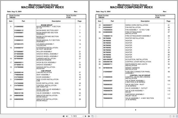
Boom Group
Boom Assembly – 4 Section
34’-104’
Boom Base Section Assy
Boom Inner Mid Section
Assembly
Boom Outer Mid Section
Assembly
Boom Manual Fly Section
Assembly
Cylinder Assembly –
Telescope
Extension Installation –
32 Foot Jib Boom
Roller Assembly
Sheave Wheel Assembly
Sheave Wheel Assembly
Carrier Installation –
Boom Extension
Hook Block Assembly
Sheave Assembly
Sheave Installation –
Rooster
Cab Group
Cab Installation
Seat Assembly
Door Assembly
Side Cover Installation –
Cab
Door Installation – Side
Control Installation –
Air Throttle
Pedal And Valve Assembly –
Accelerator
Valve Assembly – Control
Indicator Installation –
Boom Angle
Indicator Installation –
Boom Angle
Swing Horn Installation
Fan Installation
Fan Assembly – 12 Volt Cab
Fire Extinguisher
Installation
Fire Extinguisher Assembly
Heater Installation
Heater
Heater
Heater
Heater
Heater
Heater
Heater
Heater
Acoustical Installation
Control Lever Installation
Instruments And Lights
Installation
Wiring Harness
Installation
Fuse And Connector Panel
Assembly
Control Valve Group
Control Valve And Linkage
Installation
Valve Bank Assembly –
4 Section (A-35 Series)
Valve Section – Inlet
(A-35 Series)
Valve Assembly – Outlet
Valve Sub-Assembly –
Relief
Cartridge Assembly –
Relief Valve
Valve Assembly – 4-Way Section
(A-35 Series)
Valve Section – Relief
Valve Assembly – Relief
Valve Section – 4 Way
(A-35 Series)
Valve Assembly – Relief
Cartridge Assembly
Cartridge Assembly –
Relief Valve
Valve Assembly – Relief
Valve Assembly – Relief
Valve Bank Assembly –
1 Section (A-35 Series)
Valve Section – Inlet
(A-35 Series)
Valve Assembly – Outlet
Valve Assembly – 4-Way Section
(A-35 Series)
Cartridge Assembly
Valve Bank Assembly –
2 Section A-20 Series
Valve Assembly – Section
Inlet (A-20 Series)
Valve Assembly – Relief
2500 Psi
Valve Assembly – Section
Outlet (A-20 Series)
Valve Section – 4 Way
Valve Assembly – 4-Way Section
Valve Assembly – Relief
Valve Assembly – Relief
2500 Psi
Valve Assembly – Relief
Valve Bank Assembly –
1 Section A-20 Series
Valve Assembly – Section
Inlet (A-20 Series)
Valve Section – Outlet
Valve Section – 4 Way
Valve Assembly – Relief
1500 Psi
Valve Assembly – Relief
1500 Psi
Valve Bank Assembly –
1 Section
Valve Assembly – Section
Inlet (A-20 Series)
Valve Assembly – Section
Outlet (A-20 Series)
Valve Section – 4 Way
Hydraulic Lines Installation –
Counterweight Removal
Supply, Pressure And
Return Hydraulic Schematic
Hydraulic Lines Installation –
Mid-Telescope
Free Swing With Trailing
Boom
Hydraulic Lines Installation –
Fly-Telescope
Grove Main Auxilary Hoist
Hydraulic Schematic
Hoist Group
Covers Installation –
Hoist Mounting Structure
Hoist Installation – Main
Hoist Assembly –
Model Ho30b-16
Motor Assembly, Hydraulic
Valve Assembly – Selector
Valve Assembly –
Motor Control
Valve Assembly –
Motor Control
Hoist Installation –
Auxiliary
Hoist Assembly –
Model Ho15b-16
Valve Assembly – Motor
Control
Gear Reduction Assembly
Motor Assembly – Hydraulic
Idler Drum Installation
Not Available As Assembly
Roller Assembly – Cable
Roller Assembly – Cable
Rotation Indicator
Installation – Model 30
Driver Assembly
Driver Assembly
Indicator Assembly
Transmitter Assembly
Rotation Indicator
Installation – Model 15
Driver Assembly
Driver Assembly
Indicator Assembly
Transmitter Assembly
Cable Follower
Installation
Cable Follower Assembly –
Hoist
Cable Follower
Cable Follower
Turntable Group
Turntable Weldment-Drive
Assembly And Installation
Swing Box And Brake Assembly
Motor Assembly – Orbit
Brake Assembly
Cylinder Installation –
Lift
Cylinder Assembly – Lift
Counterweight Installation
Cylinder Assembly –
Counterweight Mover
Reel Installation – Hose
Hose Reel Assembly –
Right Hand
Hose Reel Assembly –
Right Hand
Lock Installation – Swing
Bearing Bolt Installation
Hydraulic Lines Installation – Lift
Air Lines Installation
Swivel Installation –
Electric/Hydraulic
Swivel Assembly –
Hydraulic
Ring Assembly – Slip
24 Conductor
Guard Installation –
Pinion
Pivot Shaft Installation –
Boom
Valve Installation –
Solenoid/Reducing
Valve Assembly – Relief
Valve Assembly – Solenoid
Valve Assembly – Solenoid
Valve Assembly – Solenoid
Swing Brake Release
Installation
Swing Brake Release
Assembly – Trailing Boom
Harness Installation
Drive Train Group
Drive Line Installation
Drive Line Assembly
Drive Line Assembly
Drive Line Assembly
Drive Line Assembly
Transmission Installation
Not Available As Assembly
Transmission Assembly
Transmission Assembly
Air System
Transmission Assembly
Main Housing Assembly
Transmission Assembly
Yokes And Bars Assembly
Transmission Assembly
Main Shaft – Countershaft
Transmission Assembly
Main Drive, Idler, Bearing
Assembly
Transmission Assembly
Cylinder Assemblies
Transmission Assembly
Auxiliary Gear Set Assemblies
Transmission Assembly
Countershaft Brake Assembly
Axle Group
Axle And Steering
Installation – Front
Drag Link And Steering
Valve Assembly
Steering Gear Assembly
Cylinder Assembly – Steer
Wheel And Drum Assembly
Arm Assembly – Torque
Axle Assembly
Axle Assembly
Axle Assembly
Brake Assembly – Right Hand
Axle Assembly
Brake Assembly – Left Hand
Cylinder Assembly – Steer
Wheel And Drum Assembly
Arm Assembly – Torque
Axle Assembly
Axle Assembly
Axle Assembly
Brake Assembly – Right Hand
Axle Assembly
Brake Assembly – Left Hand
Suspension Assembly
Axle Installation – Rear
Wheel And Drum Assembly
Axle Assembly
Axle Assembly
Differential Carrier Assembly
Axle Assembly
Carrier Assembly
Axle Assembly
Right And Left Brake
Assemblies
Axle Assembly
Axle Assembly – Front, Rear
Axle Assembly
Failsafe Chamber Assembly
Axle Assembly – Rear Rear
Axle Assembly – Rear Rear
Differential Carrier Assembly
Axle Assembly – Rear Rear
Brake Assembly
Axle Assembly – Rear Rear
Axle Assembly
Axle Assembly – Rear Rear
Failsafe Brake Chamber
Assembly
Shaft Assembly –
Inner Axle
Hydraulic Lines Installation –
Power Steering
Valve Extension
Installation – Tire
Tire And Wheel Assembly
Tire And Wheel Assembly
Outrigger Group
Outrigger Installation
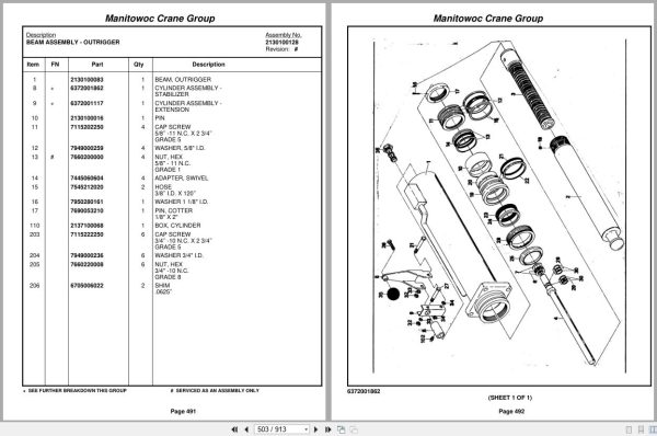
Beam Assembly – Outrigger
Cylinder Assembly –
Stabilizer
Cylinder Assembly –
Extension
Hydraulic Lines Installation –
Outrigger
Valve Installation – Control
– Outrigger
Valve Assembly – 4 Stack
Outrigger Solenoid
Valve Assembly – Selector
Valve Assembly – Solenoid
Pad And Storage
Installation – Outrigger
Float Assembly – Outrigger
Frame Group
Fenders And Battery Box
Installation – Front
Fender Installation – Rear
Fuel Tank Installation
Reservoir Installation –
Hydraulic
Filter Assembly – Oil
Lights And Horn
Installation – Exterior
Hydraulic Lines Installation –
Supply, Pressure And Return
Valve Assembly – Sequence
Air System Schematic
Air Tank And Valve
Installation
Dryer Assembly – Air
Valve Assembly –
Spring Brake
Reservoir Installation –
Power Steering
Reservoir Assembly –
Power Steering
Support Installation –
Tube
Support Installation –
Tube
Hydraulic Lines Installation –
Supply, Pressure And Return
Support Installation –
Tube
Mud Guard Installation
Ladder Installation –
Access
Ladder Installation –
Jib Access
Alarm Installation –
Back-Up
Air Brake And Electrical
Disconnect Installation
Hydraulic Lines Installation –
Air System Disconnect
Wiring Diagram-Electrical
Disconnect
Decal Installation
Electrical Harness
Installation-Carrier
Cab Carrier Group
Cab Installation
Cab Assembly
Door Assembly
Heater Assembly –
Hot Water
Steering Column Assembly
Complete Assembly
Valve Assembly – Dual Brake
Instruments And Lights
Installation
Wiper Installation –
Windshield
Not Available As Assembly
Mirror Installation –
Rear View
Mirror Head And Loop
Assembly – Stainless Steel
Acoustical Installation
Stabilizer Installation –
Cab
Fan Installation – Cab
Circulating
Fan Assembly – 12 Volt Cab
Complete Assembly
Engine Carrier Group
Battery Installation
Engine Installation –
Gm 6-71
Quick Start Installation
Radiator And Oil Cooler
Installation
Shift Installation – Transmission
Not Available As Assembly
Master Control Unit
Assembly
Battery Installation
Throttle Installation
Gmc 6-71n
Wiring Diagram
Valve Assembly – Relay
Fuel/Water Separater
Installation
Fuel/Water Separater
Assembly
Valve Assembly –
Flow Divider
Controller Assembly –
Slave Unit
Pump And Manifold
Installation
Pump Assembly – Two Section
Drive Assembly – Pump
Hydraulic Suction Tube
Installation
Not Available As Assembly
Drive Line Assembly
Hood Installation – Engine
Master And Slave Cylinder
Installation – Clutch
Cylinder Assembly – Master
Exhaust System
Installation
Cleaner Installation – Air
Cleaner Assembly – Air
Complete Assembly
Schematic
Wiring Diagram
S/S Wiring Diagram

REALEASE :
REALEASE :

REALEASE :
REALEASE :

REALEASE :
REALEASE :

REALEASE :
REALEASE :

REALEASE :
REALEASE :

REALEASE :
REALEASE :

REALEASE :
REALEASE :

REALEASE :
REALEASE :
Automotive - Heavy Equipment - Truck & Bus - Forklift - Crane