
7 ITEMSVIEW CART


Total: 250.00
Expert Support
Full Speed
100% Working
30 USD
Contents:
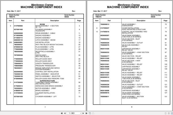
Boom
Boom Assembly – 4 Section
35′- 110′
Cylinder Assembly –
Telescope
Drum Assembly – Cable
Sheave Assembly
Sheave Assembly
Latch Assembly – Boom
Lmi Installation
Anti-Two Block Weight W/Chain
Plug Assembly – 6 Pin
Plug Assembly – 6 Pin
Receptacle Assembly –
6 Pin
Switch Assy,
Anti-Two Block
Roller Guide Assy
Roller Guide Assy
Length Transducer
Pressure Transducer
Bridge Amplifier And Servo
System Assembly
Control Unit Installation
Panel Assembly – Indicator
Switch Assembly – Selector
Roller Guide Assy Rework 77300
Superstructure
Turntable Drive Assembly
And Installation
Swing Box And Brake Assembly
Motor Assembly – Orbit
Brake Assembly
Cylinder Installation –
Lift
Cylinder Assembly – Lift
Valve Assembly –
Overcenter
Cover Installation –
Hoist Mounting Structure
Control Valve Assembly And
Installation
Valve Bank Assembly –
4 Section (A-35 Series)
Valve Section – Inlet
(A-35 Series)
Valve Assembly – Outlet
Valve Sub-Assembly –
Relief
Cartridge Assembly –
Relief Valve
Valve Assembly – 4-Way Section
(A-35 Series)
Valve Section – Relief
Valve Assembly – Relief
Valve Section – 4 Way
(A-35 Series)
Valve Assembly – Relief
Cartridge Assembly
Cartridge Assembly –
Relief Valve
Valve Assembly – Relief
Valve Assembly – Relief
Valve Bank Assembly –
1 Section (A-35 Series)
Valve Section – Inlet
(A-35 Series)
Valve Assembly – Outlet
Valve Assembly – 4-Way Section
(A-35 Series)
Cartridge Assembly
Valve Bank Assembly –
2 Section A-20 Series
Valve Assembly – Section
Inlet (A-20 Series)
Valve Assembly – Relief
2500 Psi
Valve Assembly – Section
Outlet (A-20 Series)
Valve Section – 4 Way
Valve Assembly – 4-Way Section
Valve Assembly – Relief
Valve Assembly – Relief
2500 Psi
Valve Assembly – Relief
Valve Bank Assembly –
1 Section A-20 Series
Valve Assembly – Section
Inlet (A-20 Series)
Valve Section – Outlet
Valve Section – 4 Way
Valve Assembly – Relief
1500 Psi
Valve Assembly – Relief
1500 Psi
Valve Bank Assembly –
2 Section A-20 Series
Valve Assembly – Section
Inlet (A-20 Series)
Valve Assembly – Section
Outlet (A-20 Series)
Valve Section – 4 Way
Valve, Relief – 1250 Psi
Hoist Installation – Main
Hoist Assembly –
Model Ho30b-16
Motor Assembly, Hydraulic
Valve Assembly – Selector
Valve Assembly –
Motor Control
Counterweight Installation
Valve Assembly – 2-Way Cam
Reel Installation – Hose
Hose Reel Assembly –
Right Hand
Hose Reel Assembly –
Right Hand
Rotation Indicator
Installation – Model 30
Driver Assembly
Driver Assembly
Indicator Assembly
Transmitter Assembly
Lock Installation – Swing
(Not Available As Assembly)
Bearing Bolt Installation
Hydraulic Lines Installation –
Supply, Pressure And Return
Hydraulic Lines Installation –
Swing
Hydraulic Lines Installation –
Mid-Tele And Counterweight
Hydraulic Lines Installation –
Fly Telescope
Hydraulic Lines Installation – Lift
Grove Main Hoist Hydraulic
Schematic
Air Lines Installation –
Swivel Installation –
Electric/Hydraulic
Swivel Assembly –
Hydraulic
Ring Assembly – Slip
24 Conductor
Follower Installation – Cable
Guard Installation –
Pinion
Shaft Installation – Pivot
Carrier Installation –
Counterweight
Cylinder Assembly –
Counterweight Mover
Roller Assembly
Superstructure Cab
Cab Installation
Seat Assembly
Door Assembly
Valve Cover Installation –
Control
Control Installation –
Air Throttle
Pedal And Valve Assembly –
Accelerator
Valve Assembly – Control
Swing Horn Installation
Control Lever Lockout
Installation
Cylinder Assembly-Lockout
Fan Installation
Fan Assembly – 12 Volt Cab
Extinguisher Installation – Fire
Fire Extinguisher Assembly
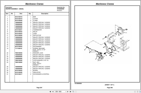
Heater Installation –
Diesel
Heater Assembly – Diesel
Heater Assembly – Diesel
Heater Assembly – Diesel
Heater Assembly – Diesel
Heater Assembly – Diesel
Heater Assembly – Diesel
Heater Assembly – Diesel
Heater Assembly – Diesel
Heater Assembly – Diesel
Acoustical Installation
Wiring Harness
Installation
Fuse And Connector Panel
Assembly
Control Lever Installation
Instruments And Lights
Installation
Lowerworks/Carrier
Engine Installation –
Gm 6-71
Quick Start Installation
Radiator And Oil Cooler
Installation
Shift Installation – Transmission
(Not Available As Assembly)
Master Control Unit
Assembly
Battery Installation
Throttle Installation
Gmc 6-71n
Wiring Diagram
Valve Assembly – Relay
Fuel/Water Separater
Installation
Fuel/Water Separater
Assembly
Valve Assembly –
Flow Divider
Controller Assembly –
Slave Unit
Axle And Steering
Installation – Front
Drag Link And Steering
Valve Assembly
Steering Gear Assembly
Cylinder Assembly – Steer
Wheel And Drum Assembly
Arm Assembly – Torque
Axle Assembly
Axle Assembly
Axle Assembly
Brake Assembly – Right Hand
Axle Assembly
Brake Assembly – Left Hand
Cylinder Assembly – Steer
Wheel And Drum Assembly
Arm Assembly – Torque
Axle Assembly
Axle Assembly
Axle Assembly
Brake Assembly – Right Hand
Axle Assembly
Brake Assembly – Left Hand
Suspension Assembly
Axle Installation – Rear
Wheel And Drum Assembly
Axle Assembly
Axle Assembly
Differential Carrier Assembly
Axle Assembly
Carrier Assembly
Axle Assembly
Right And Left Brake
Assemblies
Axle Assembly
Axle Assembly – Front, Rear
Axle Assembly
Failsafe Chamber Assembly
Axle Assembly – Rear Rear
Axle Assembly – Rear Rear
Differential Carrier Assembly
Axle Assembly – Rear Rear
Brake Assembly
Axle Assembly – Rear Rear
Axle Assembly
Axle Assembly – Rear Rear
Failsafe Brake Chamber
Assembly
Shaft Assembly –
Inner Axle
Outrigger Beam
Installation
Cylinder Assembly –
Stabilizer
Cylinder Assembly –
Extension
Fenders And Battery Box
Installation – Front
Fender Installation – Rear
Fuel Tank Installation
Reservoir Installation –
Hydraulic
Filter Assembly – Oil
Drive Line Installation
Drive Line Assembly
Horizontal Shaft
Drive Line Assembly
Lights And Horn
Installation – Exterior
Hydraulic Lines Installation –
Supply, Pressure And Return
Valve Assembly – Sequence
Hydraulic Lines Installation –
Outrigger
Hydraulic Lines Installation –
Power Steering
Air System Schematic
Air Tank And Valve
Installation
Dryer Assembly – Air
Valve Assembly –
Spring Brake
Valve Installation – Control
– Outrigger
Valve Assembly – 4 Stack
Outrigger Solenoid
Valve Assembly – Outrigger Selector
(Complete Assembly)
Valve Assembly – Solenoid
Reservoir Installation –
Power Steering
Reservoir Assembly –
Power Steering
Rest Installation – Boom
Support Installation –
Tube
Support Installation –
Tube
Hydraulic Lines Installation –
Supply, Pressure And Return
Support Installation –
Tube
Mud Guard Installation
Ladder Installation –
Access
Ladder Installation –
Jib Access
Valve Extension
Installation – Tire
Tire And Wheel Assembly
Tire And Wheel Assembly
Hood Installation – Engine
Master And Slave Cylinder
Installation – Clutch
Cylinder Assembly – Master
Electrical Harness
Installation-Carrier
Exhaust System
Installation
Cleaner Installation – Air
Cleaner Assembly – Air
(Complete Assembly)
Pump And Manifold
Installation
Pump Assembly – 2 Section
Drive Assembly – Pump
Drive Line Assembly
Transmission Installation
– Fuller
Transmission Assembly
Transmission Assembly
Air System
Transmission Assembly
Main Housing Assembly
Transmission Assembly
Yokes And Bars Assembly
Transmission Assembly
Main Shaft – Countershaft
Transmission Assembly
Main Drive, Idler, Bearing
Assembly
Transmission Assembly
Cylinder Assembly
Transmission Assembly
Auxiliary Gear Set Assemblies
Transmission Assembly
Brake Assembly – Countershaft
Float Assembly – Outrigger
(Complete Assembly)
Valve Installation –
Pressure Reducing
Valve Assembly – Relief
Valve Assembly – Solenoid
Carrier/Frame Cab
Cab Installation
Cab Assembly
Door Assembly
Heater Assembly –
Hot Water
Steering Column Assembly
(Complete Assembly)
Valve Assembly – Dual Brake
Instruments And Lights
Installation
Mirror Installation –
Rear View
Mirror Head And Loop
Assembly – Stainless Steel
Stabilizer Installation –
Cab
Acoustical Installation
Specs/Schematics
Wiring Diagram
S/S Wiring Diagram
Decals
Decal Installation

REALEASE :
REALEASE :

REALEASE :
REALEASE :

REALEASE :
REALEASE :

REALEASE :
REALEASE :

REALEASE :
REALEASE :

REALEASE :
REALEASE :

REALEASE :
REALEASE :

REALEASE :
REALEASE :
 Automotive - Heavy Equipment - Truck & Bus - Forklift - Crane