
1 ITEMVIEW CART

Total: 20.00

Expert Support
Full Speed
100% Working
40 USD
Contents:
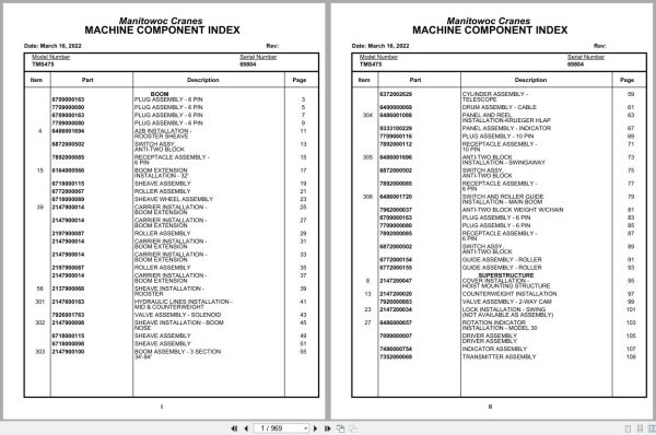
Boom
Plug Assembly – 6 Pin
Plug Assembly – 6 Pin
Plug Assembly – 6 Pin
Plug Assembly – 6 Pin
A2b Installation –
Rooster Sheave
Switch Assy,
Anti-Two Block
Receptacle Assembly –
6 Pin
Boom Extension
Installation – 32′
Sheave Assembly
Roller Assembly
Sheave Wheel Assembly
Carrier Installation –
Boom Extension
Carrier Installation –
Boom Extension
Roller Assembly
Carrier Installation –
Boom Extension
Carrier Installation –
Boom Extension
Roller Assembly
Carrier Installation –
Boom Extension
Sheave Installation –
Rooster
Hydraulic Lines Installation –
Mid & Counterweight
Valve Assembly – Solenoid
Sheave Installation – Boom
Nose
Sheave Assembly
Sheave Assembly
Boom Assembly – 3 Section
34′-84′
Cylinder Assembly –
Telescope
Drum Assembly – Cable
Panel And Reel
Installation-Krueger Hlap
Panel Assembly – Indicator
Plug Assembly – 10 Pin
Receptacle Assembly –
10 Pin
Anti-Two Block
Installation – Swingaway
Switch Assy,
Anti-Two Block
Receptacle Assembly –
6 Pin
Switch And Roller Guide
Installation – Main Boom
Anti-Two Block Weight W/Chain
Plug Assembly – 6 Pin
Plug Assembly – 6 Pin
Receptacle Assembly –
6 Pin
Switch Assy,
Anti-Two Block
Guide Assembly – Roller
Guide Assembly – Roller
Superstructure
Cover Installation –
Hoist Mounting Structure
Counterweight Installation
Valve Assembly – 2-Way Cam
Lock Installation – Swing
(Not Available As Assembly)
Rotation Indicator
Installation – Model 30
Driver Assembly
Driver Assembly
Indicator Assembly
Transmitter Assembly
Rotation Indicator
Installation – Model 30
Driver Assembly
Driver Assembly
Indicator Assembly
Transmitter Assembly
Bearing Bolt Installation
Horn Installation – Swing
Hydraulic Lines Installation –
Fly Telescope
Hydraulic Lines Installation – Lift
Guard Installation –
Pinion
Cable Follower
Installation
Shaft Installation – Pivot
Carrier Installation –
Counterweight
Cylinder Assembly –
Counterweight Mover
Roller Assembly
Follower Installation – Cable
Control Valve And Linkage
Installation
Valve Assembly – 1 Section Control
Valve Section – 4 Way
Check, Anti-Cavitation
Valve Section – Inlet
Cartridge, Relief –
1500 Psi
Valve Bank Assembly –
4 Section (A-35 Series)
Valve Assembly – Outlet
Valve Section – Inlet
(A-35 Series)
Cartridge Assembly –
Relief Valve
Valve Assembly – Relief
1000 Psi
Cartridge Assembly
Valve Bank Assembly –
2 Section (A-20 Series)
Valve Assembly – Section
Inlet (A-20 Series)
Valve Assembly – Relief
2500 Psi
Valve Assembly – Relief
2500 Psi
Valve Bank Assembly –
2 Section (A-35 Series)
Valve Assembly – Outlet
Valve Section – Inlet
(A-35 Series)
Cartridge Assembly
Cylinder Assembly –
Lockout
Valve Assembly –
Pressure And Sequence
Valve Assembly – Solenoid
Hydraulic Lines Installation –
Main And Auxiliary Hoist
Hoist Installation – Main
Hoist Assembly –
Model Ho-30b-16
Valves And Plumbing
Installation – Hoist
(Not Available As Assembly)
Valve Assembly –
Motor Control
Valve Assembly – Selector
Motor Assembly – Hydraulic
Brake Assembly
Cylinder Assembly – Air
Hoist Installation –
Auxiliary
Hoist Assembly –
Model Ho-30b-16
Valves And Plumbing
Installation – Hoist
(Not Available As Assembly)
Valve Assembly –
Motor Control
Valve Assembly – Selector
Motor Assembly – Hydraulic
Brake Assembly
Cylinder Assembly – Air
Air Lines Installation –
Turntable Drive
Installation
Swing Box Assembly –
Complete
Motor Assembly – Orbit
Brake Assembly
Cylinder Installation –
Lift
Cylinder Assembly – Lift
Valve Assembly –
Overcenter
Hydraulic Lines Installation –
Supply, Pressure And Return
Valve Assembly – Check
Hydraulic Lines Installation –
Supply, Pressure And Return
Valve Assembly – Sequence
Hydraulic Lines Installation –
Free Swing
Swivel Installation
– Electric/Hydraulic
Swivel Assembly –
Hydraulic
Ring Assembly – Slip
Cylinder Assembly – Lift
Valve Installation –
Counterweight Removal
Valve Bank Assembly –
2 Section – (A-20 Series)
Valve Section – Outlet
Valve Section – Inlet
( A20 Series )
Valve, Relief – 1250 Psi
Valve, Relief – 1250 Psi
Superstructure Cab
Cab Installation
Cab Weldment And Assembly
Valve Assembly –
Selector
Valve Cover Installation –
Control
Control Installation –
Air Throttle
Pedal And Valve Assembly –
Accelerator
Valve Assembly – Control
Weatherstrip Installation
– Cab
Electrical System
Installation – S/S
Panel Assembly – S/S
Fuse And Connector
Fan Installation – Cab
Circulating
Fan Assembly – 12 Volt Cab
(Complete Assembly)
Extinguisher Installation – Fire
Washer Installation –
Windshield
Acoustical Installation
Valve And Pedal
Installation – Swing Brake
Valve Assembly –
Power Brake
Seat Assembly
Wiper Installation –
Cab Windshield
Instruments And Lights
Installation
Warning System
Installation-Audio/Visual
Control Lever
Installation
Seat Installation
Seat Assembly
Grab Rail Installation
Plate, Mounting
Installation – Load Chart
Heater Installation –
Propane
Heater Assembly – Propane
Heater Assembly – Propane
Heater Assembly – Propane
Heater Assembly – Propane
Heater Assembly – Propane
Heater Assembly – Propane
Heater Assembly – Propane
Heater Assembly – Propane
Heater Assembly – Propane
Heater Assembly – Propane
Heater Assembly – Propane
Heater Assembly – Propane
Heater Assembly – Propane
Heater Assembly – Propane
Hydraulic Lines Installation –
Control Lever Lockout
Carrier/Lowerworks
Fenders And Battery Box
Installation – Front
Fuel Tank Installation
Reservoir Installation –
Hydraulic
Filter Assembly – Oil
Lights And Horn
Installation – Exterior
Hydraulic Lines Installation –
Power Steering
Air System Schematic
Air Tank And Valve
Installation
Dryer Assembly – Air
Valve Assembly –
Spring Brake
Reservoir Installation –
Power Steering
Reservoir Assembly –
Power Steering
Rest Installation – Boom
Ladder Installation –
Access
Ladder Installation –
Jib Access
Alarm Installation –
Back-Up
Valve Extension
Installation – Tire
Tire And Wheel Assembly
Hood Installation – Engine
Master And Slave Cylinder
Installation – Clutch
Cylinder Assembly – Master
Electrical System
Installation – Carrier
Panel Assembly –
Fuse And Connector
Harness Assembly –
P.C. Board Carrier
Exhaust System
Installation
Fender Installation – Rear
Cleaner Installation – Air
Cleaner Assembly – Air
(Complete Assembly)
Cylinder Installation –
Front Stabilizer
Cylinder Assembly –
Stabilizer
Pad And Storage
Installation – Outrigger
Support Installation –
Tube
Support Installation –
Tube
Hydraulic Lines Installation –
Supply, Pressure And Return
Support Installation –
Tube
Mud Guard Installation
Transmission Installation
– Fuller
Transmission Assembly
Transmission Assembly
Air System
Transmission Assembly
Main Housing Assembly
Transmission Assembly
Yokes And Bars Assembly
Transmission Assembly
Main Shaft – Countershaft
Transmission Assembly
Main Drive, Idler, Bearing
Assembly
Transmission Assembly
Cylinder Assembly
Transmission Assembly
Auxiliary Gear Set Assemblies
Transmission Assembly
Brake Assembly – Countershaft
Float Assembly – Outrigger
Belt & Filter Cumm Ntcc 240
Drive Line Installation
Drive Line Assembly
Horizontal Shaft
Drive Line Assembly
Axle And Steering
Installation – Front
Valve Assembly – Steering
Steering Gear Assembly
Cylinder Assembly – Steer
Wheel And Drum Assembly
Arm Assembly – Torque
Axle Assembly
Axle And Wheel End Group
Axle Brake Assy. L.H. Group
Axle Brake Assy. R.H. Group
Brake Chamber Assy. Group
Brake Chamber Assy. Group
Cylinder Assembly – Steer
Wheel And Drum Assembly
Arm Assembly – Torque
Axle Assembly
Axle Assembly
Axle And Wheel End Parts
Axle Assembly
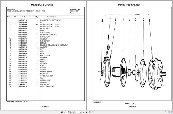
Brake Assembly – Left Hand
Axle Assembly
Brake Assembly – Right Hand
Axle Assembly
Brake Chamber Assembly
Axle Assembly
Brake Chamber Assembly
Suspension Assembly
Axle Installation – Rear
Axle Bearing – Rear
Beam Assembly – Equalizer
Adapter Assembly
Wheel And Drum Assembly
Axle Assembly
Axle Assembly
Differential Carrier Parts
Axle Assembly
Housing Parts
Axle Assembly
Brake Assembly – Left Hand
Axle Assembly
Brake Assembly – Right Hand
Axle Assembly
Brake Chamber Assembly
Axle Assembly
Brake Chamber Assembly
Axle Assembly
Axle Assembly
Differential Carrier Parts
Axle Assembly
Housing Parts
Axle Assembly
Brake Assembly – Left Hand
Axle Assembly
Brake Assembly – Right Hand
Axle Assembly
Brake Chamber Assembly
Axle Assembly
Brake Chamber Assembly
Drive Line Assembly
Rod Assembly – Torque
Tire And Wheel Assembly
Outrigger Beam
Installation
Cylinder Assembly –
Stabilizer
Cylinder Assembly –
Extension
Hydraulic Lines Installation –
Outrigger
Valve Installation – Control
– Outrigger
Valve Assembly – Outrigger Selector
(Complete Assembly)
Valve Assembly – 4 Stack
Outrigger Solenoid
Valve Assembly – Solenoid
Valve Assembly – 5 Stack
Valve Assembly – Relief
Pump And Manifold
Installation
Pump Assembly – 2 Section
Drive Assembly – Pump
Drive Line Assembly
Engine Installation –
Cummins Ntcc-240
Fuel/Water Separater
Assembly
Cylinder Assembly – Throttle
Tachometer Generator
Assembly
Pump Assembly –
Power Steering
Valve Assembly –
Flow Divider
Controller Assembly –
Slave Unit
Carrier/Frame Cab
Throttle Pedal
Installation
Accelerator Pedal Assy
Accelerator Pedal Design “B”
Accelerator Pedal Design “A”
Acoustical Installation
(Carrier Cab)
Stabilizer Installation –
Cab
Mirror Installation –
Rear View
Mirror Head And Loop
Assembly – Stainless Steel
Warning System
Installation-Audio/Visual
Cab Installation
Cab Weldment And Assembly
Door Assembly
Door Assembly
Heater Assembly –
Hot Water
Steering Column Assembly
Valve Assembly – Dual Brake
Instruments And Lights
Installation
Harness Assembly –
Instruments And Lights
Specs/Schematics
Wiring Diagram – Krueger
Decals
Decal Installation

REALEASE :
REALEASE :

REALEASE :
REALEASE :

REALEASE :
REALEASE :

REALEASE :
REALEASE :

REALEASE :
REALEASE :

REALEASE :
REALEASE :

REALEASE :
REALEASE :

REALEASE :
REALEASE :
Automotive - Heavy Equipment - Truck & Bus - Forklift - Crane