
1 ITEMVIEW CART

Total: 250.00
Expert Support
Full Speed
100% Working
15 USD
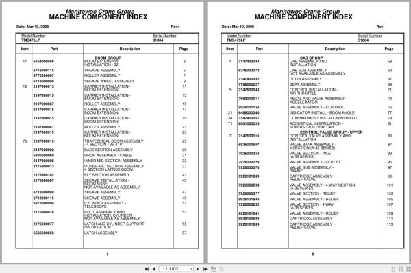
Contents:
Boom Group
Boom Extension
Installation – 32’
Sheave Assembly
Roller Assembly
Sheave Wheel Assembly
Carrier Installation –
Boom Extension
Carrier Installation –
Boom Extension
Roller Assembly
Carrier Installation –
Boom Extension
Carrier Installation –
Boom Extension
Roller Assembly
Carrier Installation –
Boom Extension
Trapezoidal Boom Assembly
– 4 Section – 35’-110’
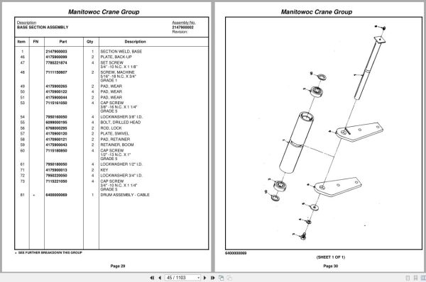
Base Section Assembly
Drum Assembly – Cable
Inner Mid Section Assembly
Outer-Mid Section Assembly
4 Section Lattice Boom
Fly Section Assembly
Sheave Installation –
Boom Nose
Not Available As Assembly
Sheave Assembly
Sheave Assembly
Cylinder Assembly –
Telescope
Foot Assembly And
Installation, Cylinder
Not Available As Assembly
Latch And Cylinder Support
Installation
Latch Assembly
Cab Group
Cab Assembly And
Installation
Cab Sub Assembly
Not Available As Assembly
Door Assembly
Seat Assembly
Control Installation –
Air Throttle
Pedal And Valve Assembly –
Accelerator
Valve Assembly – Control
Indicator Install – Boom Angle
Compartment Install-Winshield
Acoustical Installation –
Superstructure Cab
Control Valve Group – Upper
Control Valve Assembly And
Installation
Valve Bank Assembly –
4 Section (A-35 Series)
Valve Section – Inlet
(A-35 Series)
Valve Assembly – Outlet
Valve Sub-Assembly –
Relief
Cartridge Assembly –
Relief Valve
Valve Assembly – 4-Way Section
(A-35 Series)
Valve Section – Relief
Valve Assembly – Relief
Valve Section – 4 Way
(A-35 Series)
Valve Assembly – Relief
Cartridge Assembly
Cartridge Assembly –
Relief Valve
Valve Assembly – Relief
Valve Assembly – Relief
Valve Bank Assembly –
1 Section (A-35 Series)
Valve Section – Inlet
(A-35 Series)
Valve Assembly – Outlet
Valve Assembly – 4-Way Section
(A-35 Series)
Cartridge Assembly
Valve Bank Assembly –
2 Section A-20 Series
Valve Assembly – Section
Inlet (A-20 Series)
Valve Assembly – Relief
2500 Psi
Valve Assembly – Section
Outlet (A-20 Series)
Valve Section – 4 Way
Valve Assembly – 4-Way Section
Valve Assembly – Relief
Valve Assembly – Relief
2500 Psi
Valve Assembly – Relief
Valve Bank Assembly –
1 Section A-20 Series
Valve Assembly – Section
Inlet (A-20 Series)
Valve Section – Outlet
Valve Section – 4 Way
Valve Assembly – Relief
1500 Psi
Valve Assembly – Relief
1500 Psi
Valve Bank Assembly –
2 Section A-20 Series
Valve Assembly – Section
Inlet (A-20 Series)
Valve Assembly – Section
Outlet (A-20 Series)
Valve Section – 4 Way
Valve, Relief – 1250 Psi
Hydraulic Lines Installation –
Supply, Pressure And Return
Swing-Hydraulic Schematic
Hydraulic Lines Installation –
Mid-Tele And Counterweight
Lines Install – Fly Tel Hyd
Hydraulic Lines Installation – Lift
Grove Main Hoist Hydraulic
Schematic
Hoist Group
Hoist Install. – Mod.30a Main
Hoist Assembly –
Model 30a
Hoist Assembly –
Model 30a-17
Motor Assembly – Hydraulic
Valve Assembly – Selector
Valve Assembly –
Motor Control
Rotation Ind.Install.(Mod.30)
Rotation Indicator
Assembly-Hoist Drum
Follower Installation – Cable
Turntable Group
Cover Install – Control Valve
Door Installation – Side
Not Available As Assembly
Cylinder Install – 11″ Lift
11’’ Lift Cyl. Ass’y.
Cylinder Assembly – Lift
Valve Assembly –
Overcenter
Swivel Install. Electric/ Hyd.
Electro/Hydraulic Swivel
Assembly
Swivel Assembly –
Hydraulic
Collector Ring Assembly –
24 Conductor
Counterweight Installation
Valve Assembly – 2-Way Cam
Hose Reel Installation
Reel Assembly – Hose
Reel Assembly – Hose
Bearing Bolt Installation
Swing Horn Installation
Air Lines Installation
Drive Install – Turntable And
Turntable And Drive
Installation
Cable Assembly – Brake
Manifold Installation –
Hydraulic
Counterweight Carrier Inst
3’’ Counterweight Mover
Cylinder Assembly
Counterweight Latch
Drive Train Group
Drive Line Installation
Drive Line Assembly
Drive Line Assembly
Drive Line Assembly
Axle Group
Front Axle And Steering
Assembly And Installation
Axle Assembly – Front
Axle Assembly – Front
Front Axle
Axle Assembly – Front
Brake Assembly
Axle Assembly – Rear
Axle Assembly – Rear
Front Axle
Axle Assembly – Rear
Brake Assembly
Suspension Assembly –
Front
Arm Assembly – Torque
Arm Assembly – Torque
Suspension Assembly
Cylinder Assembly – Steer
Drag Link And Steering
Valve Assembly
Steering Gear Assembly
Axle Installation – Rear
Axle Assembly –
Rear Tandem
Axle Assembly –
Rear Tandem
Front/Front
Axle Assembly –
Rear Tandem
Rear/Rear
Axle Assembly –
Rear Tandem
Axle Shaft Group
Axle Assembly –
Rear Tandem
Brake Assembly
Axle Assembly –
Rear Tandem
Fail Safe Chamber Assembly
Air Lines Installation – Rear
Axle
Not Available As Assembly
Outrigger Group
Outrigger Extension Beam
Assembly And Installation
Cylinder Assembly –
Stabilizer
Cylinder Assembly –
Extension
Frame Group
Front Fenders & Batt.Box Insta
Fender Installation – Rear
Tank Installation – Fuel
Hydraulic Reservoir Assy.
Reservoir Weld & Assy, Hyd
Filter Sub Assembly
Filter Assembly – Oil
Filter Sub Assembly
Filter Assembly – Oil
Lights And Horn
Installation – Exterior
Terminal Block Assembly – Electrical
Hydraulic Lines Installation –
Supply, Pressure And Return
Valve Assembly – Relief
Air System Schematic
Valve Assembly – Check
Air Tank Installation
Not Available As Assembly
Valve Assembly – Relay
Valve Assembly –
Quick Release
Support Installation –
Tube
Support Installation –
Tube
Hydraulic Lines Installation –
Supply, Pressure And Return
Support Installation –
Tube
Tms475 Final Assy –
Carrier
Engine Installation
Engine Assembly –
Gmc 6-71n
Not Available As Assembly
Cylinder Assembly – Throttle
Valve Assembly – Control
Controller Assembly –
Slave Unit
Cylinder Installation –
Clutch And Slave
Clutch Assembly
Cylinder Assembly – Slave
Quick Start Installation
Exhaust System
Installation
Cleaner Installation – Air
Cleaner Assembly – Air
Complete Assembly
Battery Installation
Not Available As Assembly
Throttle Installation
Gmc 6-71n
Diagram
Front Axle And Steering
Assembly And Installation
Axle Assembly – Front
Axle Assembly – Front
Front Axle
Axle Assembly – Front
Brake Assembly
Axle Assembly – Rear
Axle Assembly – Rear
Front Axle
Axle Assembly – Rear
Brake Assembly
Suspension Assembly –
Front
Arm Assembly – Torque
Arm Assembly – Torque
Suspension Assembly
Cylinder Assembly – Steer
Drag Link And Steering
Valve Assembly
Steering Gear Assembly
Axle Installation – Rear
Axle Assembly – Front Rear
Axle Assembly – Front Rear
Axle Assembly
Axle Assembly – Front Rear
Brake Assembly
Axle Assembly – Front Rear
Wedge Assembly
Axle Assembly – Front Rear
Brake Chamber Assembly
Axle Assembly – Rear Rear
Axle Assembly – Rear Rear
Brake Assembly
Axle Assembly – Rear Rear
Wedge Assembly
Axle Assembly – Rear Rear
Brake Chamber Assembly
Shaft Assembly –
Inner Axle
Cab And Sheet Metal
Installation – Carrier
Cab
Door Assembly
Door Assembly
Controls Installation –
Carrier
Steering Column Assembly
Complete Assembly
Valve Assembly – Dual Brake
Cylinder Assembly – Master
Seat And Seat Belt
Installation
Not Available As Assembly
Seat Assembly – Drivers
Shock
Engine Hood Assembly
Heater Assembly
Alcohol Evaporator
Installation
Not Available As Assembly
Evaporator Assembly
Valve Assembly – Check
Outrigger Extension Beam
Assembly And Installation
Cylinder Assembly –
Stabilizer
Cylinder Assembly –
Extension
Constant Speed Pump
Installation
Pump Assembly –
Two Section
Drive Assembly – Pump
Drive Line Assembly
Fenders And Battery Box
Installation – Front
Fender Installation – Rear
Tank Installation – Fuel
Hydraulic Reservoir
Installation
Oil Filter,Hydraulic
Drive Line Installation
Drive Line Assembly
Drive Line Assembly
Drive Line Assembly
Lights Install – Instruments &
Valve Assembly – Control
Lights And Horn
Installation – Exterior
Wiring Diagram
Hydraulic Lines Installation –
Supply, Pressure And Return
Valve Assembly – Relief
Hydraulic Lines Installation –
Outrigger
Hydraulic Lines Installation –
Power Steering
Air System Schematic
Valve Assembly – Check
Air Tank Installation
Valve, Relay
Valve Assembly – Check
Valve Assembly –
Spring Brake
Valve Installation – Control
– Outrigger
Valve Assembly – 4 Stack
Outrigger Solenoid
Valve Assembly – Selector
Valve Assembly – Solenoid
Reservoir Installation –
Power Steering
Used W/Gmc 8v-71n Engine
(Optional Item)
Not Available As Assembly
Pad And Storage
Installation – Outrigger
Mirror Installation –
Rear View
Mirror Head And Loop
Assembly – Stainless Steel
Support Installation –
Tube
Support Installation –
Tube
Hydraulic Lines Installation –
Supply, Pressure And Return
Support Installation –
Tube
Mud Guard Installation
Ladder Installation –
Access
Jib Access Ladder Installation
Alarm Installation –
Back-Up
Air Brake And Electrical
Disconnect Installation
Hydraulic Lines Installation –
Air System Disconnect
Wiring Diagram-Electrical
Disconnect
Air Conditioning
Installation
Condenser Assembly
Evaporator Assembly
Compressor Assembly
Clutch Assembly
Valve Extension
Installation – Tire
Tire And Wheel Assembly
Tire And Wheel Assembly
Swivel Installation –
Electric/Hydraulic
Swivel Assembly –
Hydraulic
Ring Assembly – Slip
24 Conductor
Hood Installation – Engine
Controls Installation –
Engine Brake
Master And Slave Cylinder
Installation – Clutch
Cylinder Assembly – Master
Electrical Harness
Installation-Carrier
Cab Carrier Group
Cab And Sheet Metal
Installation – Carrier
Cab
Door Assembly
Door Assembly
Controls Installation –
Carrier
Steering Column Assembly
Complete Assembly
Valve Assembly – Dual Brake
Cylinder Assembly – Master
Seat And Seat Belt
Installation
Not Available As Assembly
Seat Assembly – Drivers
Shock
Engine Hood Assembly
Heater Assembly
Lights Install – Instruments &
Valve Assembly – Control
Wiper Installation –
Windshield
Not Available As Assembly
Mirror Installation –
Rear View
Mirror Head And Loop
Assembly – Stainless Steel
Acoustical Installation
Engine Carrier Group
Engine Installation
Engine Assembly –
Gmc 6-71n
Not Available As Assembly
Cylinder Assembly – Throttle
Valve Assembly – Control
Controller Assembly –
Slave Unit
Cylinder Installation –
Clutch And Slave
Clutch Assembly
Cylinder Assembly – Slave
Quick Start Installation
Exhaust System
Installation
Cleaner Installation – Air
Cleaner Assembly – Air
Complete Assembly
Battery Installation
Not Available As Assembly
Throttle Installation
Gmc 6-71n
Diagram
Alcohol Evaporator
Installation
Not Available As Assembly
Evaporator Assembly
Valve Assembly – Check
Pump Install – Constant Speed
Pump Assembly –
Two Section
Drive Assembly – Pump
Hydraulic Suction Tube
Installation
Not Available As Assembly
Drive Line Assembly
Drive Line Assembly
Hydraulic Lines Installation –
Power Steering
Neutral Safety Switch
Installation
Control Valve Group – Lower
Hydraulic Lines Installation –
Outrigger
Valve Installation – Control
– Outrigger
Valve Assembly – 4 Stack
Outrigger Solenoid
Valve Assembly – Selector
Valve Assembly – Solenoid
Schematic
Wiring Diagram – Carrier
Wiring Diagram – S/S

REALEASE :
REALEASE :

REALEASE :
REALEASE :

REALEASE :
REALEASE :

REALEASE :
REALEASE :

REALEASE :
REALEASE :

REALEASE :
REALEASE :

REALEASE :
REALEASE :

REALEASE :
REALEASE :
 Automotive - Heavy Equipment - Truck & Bus - Forklift - Crane