
0 ITEMSVIEW CART

✓
Expert Support
✓
Full Speed
✓
100% Working
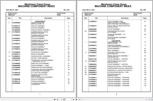
Grove Crane TMS475LP 32529 Parts Manual 2007
Size: 6.29 MB
Format: PDF
Language: English
Brand: Grove
Type of Machine: Crane
Type of Manual: Parts Manual
Model: Grove TMS475LP Crane
Serial Number: 32529
Publication Date: 2007
Number of Pages: 857 Pages
20 USD
- Description
Description
Contents:
Boom Group
Boom Extension
Installation – 32’
Sheave Assembly
Roller Assembly
Sheave Wheel Assembly
Carrier Installation –
Boom Extension
Carrier Installation –
Boom Extension
Roller Assembly
Carrier Installation –
Boom Extension
Carrier Installation –
Boom Extension
Roller Assembly
Carrier Installation –
Boom Extension
Hook Block Assembly
Sheave Assembly
Headache Ball Assembly
Socket, Open Wedge
Trapezoidal Boom Assembly
– 4 Section – 35’-110’
Base Section Assembly
Drum Assembly – Cable
Inner Mid Section Assembly
Outer-Mid Section Assembly
4 Section Lattice Boom
Fly Section Assembly
Sheave Installation –
Boom Nose
(Not Available As Assembly)
Sheave Assembly
Sheave Assembly
Cylinder Assembly –
Telescope
Foot Assembly And
Installation, Cylinder
(Not Available As Assembly)
Latch And Cylinder Support
Installation
Latch Assembly
Jib Boom Installation –
24’ A-Frame
Jib Boom Assembly – 24’
A-Frame
Sheave Wheel Assembly
3/4’’ Cable
Cab Group
Cab Assembly And
Installation
Cab Sub Assembly
(Not Available As Assembly)
Door Assembly
Seat Assembly
Control Installation –
Air Throttle
Pedal And Valve Assembly –
Accelerator
Valve Assembly – Control
Instruments And Lights
Installation
Valve Assembly – Control
Indicator Install – Boom Angle
Compartment Install-Winshield
Windshield / Defroster Install
Extinguisher Install – Fire
Propane Heater
Installation
Heater Assembly – Propane
Heater Assembly – Propane
Heater Assembly – Propane
Heater Assembly – Propane
Heater Assembly – Propane
Heater Assembly – Propane
Heater Assembly – Propane
Acoustical Installation –
Superstructure Cab
Control Valve Group – Upper
Control Valve Assembly And
Installation
Valve Bank Assembly –
4 Section (A-35 Series)
Valve Section – Inlet
(A-35 Series)
Valve Assembly – Outlet
Valve Sub-Assembly –
Relief
Cartridge Assembly –
Relief Valve
Valve Assembly – 4-Way Section
(A-35 Series)
Valve Section – Relief
Valve Assembly – Relief
Valve Section – 4 Way
(A-35 Series)
Valve Assembly – Relief
Cartridge Assembly
Cartridge Assembly –
Relief Valve
Valve Assembly – Relief
Valve Assembly – Relief
Valve Bank Assembly –
1 Section (A-35 Series)
Valve Section – Inlet
(A-35 Series)
Valve Assembly – Outlet
Valve Assembly – 4-Way Section
(A-35 Series)
Cartridge Assembly
Valve Bank Assembly –
2 Section A-20 Series
Valve Assembly – Section
Inlet (A-20 Series)
Valve Assembly – Relief
2500 Psi
Valve Assembly – Section
Outlet (A-20 Series)
Valve Section – 4 Way
Valve Assembly – 4-Way Section
Valve Assembly – Relief
Valve Assembly – Relief
2500 Psi
Valve Assembly – Relief
Valve Bank Assembly –
1 Section A-20 Series
Valve Assembly – Section
Inlet (A-20 Series)
Valve Section – Outlet
Valve Section – 4 Way
Valve Assembly – Relief
1500 Psi
Valve Assembly – Relief
1500 Psi
Valve Bank Assembly –
2 Section A-20 Series
Valve Assembly – Section
Inlet (A-20 Series)
Valve Assembly – Section
Outlet (A-20 Series)
Valve Section – 4 Way
Valve, Relief – 1250 Psi
Hydraulic Lines Installation –
Supply, Pressure And Return
Swing-Hydraulic Schematic
Hydraulic Lines Installation –
Mid-Tele And Counterweight
Lines Install – Fly Tel Hyd
Hydraulic Lines Installation – Lift
Hydraulic Lines Installation –
Main And Auxiliary Hoist
Hoist Group
Hoist Install – Model 30a Main
Hoist Assembly –
Model 30a
Hoist Assembly –
Model 30a-17
Motor Assembly – Hydraulic
Valve Assembly – Selector
Valve Assembly –
Motor Control
Rotation Ind.Install.(Mod.30)
Rotation Indicator
Assembly-Hoist Drum
Rotation Indicator Install
Follower Installation – Cable
Hoist Instal- Model 15s-16 Aux
Hoist Assembly –
Model 15a-16
Gear Reduction Assembly
Motor Assembly – Hydraulic
Tubing Installation
Turntable Group
Cover Install – Control Valve
Door Installation – Side
(Not Available As Assembly)
Cylinder Install – 11″ Lift
11’’ Lift Cyl. Ass’y.
Cylinder Assembly – Lift
Valve Assembly –
Overcenter
Swivel Install. Electric/ Hyd.
Electro/Hydraulic Swivel
Assembly
Swivel Assembly –
Hydraulic
Collector Ring Assembly –
24 Conductor
Counterweight Installation
Valve Assembly – 2-Way Cam
Hose Reel Installation
Reel Assembly – Hose
Reel Assembly – Hose
Bearing Bolt Installation
Swing Horn Installation
Air Lines Installation
Drive Install – Turntable And
Turntable And Drive
Installation
Cable Assembly – Brake
Manifold Installation –
Hydraulic
Counterweight Carrier Inst
3’’ Counterweight Mover
Cylinder Assembly
Counterweight Latch
Drive Train Group
Drive Line Installation
Drive Line Assembly
Drive Line Assembly
Drive Line Assembly
Axle Group
Front Axle And Steering
Assembly And Installation
Axle Assembly – Front
Axle Assembly – Front
Front Axle
Axle Assembly – Front
Brake Assembly
Axle Assembly – Rear
Axle Assembly – Rear
Front Axle
Axle Assembly – Rear
Brake Assembly
Suspension Assembly –
Front
Arm Assembly – Torque
Arm Assembly – Torque
Suspension Assembly
Cylinder Assembly – Steer
Drag Link And Steering
Valve Assembly
Steering Gear Assembly
Axle Installation – Rear
Axle Assembly –
Rear Tandem
Axle Assembly –
Rear Tandem
Front/Front
Axle Assembly –
Rear Tandem
Rear/Rear
Axle Assembly –
Rear Tandem
Axle Shaft Group
Axle Assembly –
Rear Tandem
Brake Assembly
Axle Assembly –
Rear Tandem
Fail Safe Chamber Assembly
Hydraulic Lines Installation –
Power Steering
(Not Available As Assembly)
Air Lines Installation – Rear
Axle
(Not Available As Assembly)
Valve Extension
Installation – Tire
Tire And Wheel Assembly
Tire And Wheel Assembly
Outrigger Group
Outrigger Extension Beam
Assembly And Installation
Cylinder Assembly –
Stabilizer
Cylinder Assembly –
Extension
Pad And Storage
Installation – Outrigger
Float Install – Aluminum O/R
Frame Group
Front Fenders & Batt.Box Insta
Fender Installation – Rear
Tank Installation – Fuel
Hydraulic Reservoir Assy.
Reservoir Weld & Assy, Hyd
Filter Sub Assembly
Filter Assembly – Oil
Filter Sub Assembly
Filter Assembly – Oil
Lights And Horn
Installation – Exterior
Terminal Block Assembly – Electrical
Hydraulic Lines Installation –
Supply, Pressure And Return
Valve Assembly – Relief
Air System Schematic
Valve Assembly – Check
Air Tank Installation
(Not Available As Assembly)
Valve Assembly – Relay
Valve Assembly –
Quick Release
Rest Installation – Boom
Reservoir Installation – Hydraulic
Hydraulic Reservoir
Weldment And Assembly
Filter Sub Assembly
Filter Assembly – Oil
Support Installation –
Tube
Support Installation –
Tube
Hydraulic Lines Installation –
Supply, Pressure And Return
Support Installation –
Tube
Mud Guard Installation
Ladder Installation –
Access
Jib Access Ladder Installation
Decal Installation –
Tms475lp
Cab Carrier Group
Cab And Sheet Metal
Installation – Carrier
Cab
Door Assembly
Door Assembly
Controls Installation –
Carrier
Steering Column Assembly
Complete Assembly
Valve Assembly – Dual Brake
Cylinder Assembly – Master
Seat And Seat Belt
Installation
(Not Available As Assembly)
Seat Assembly – Drivers
Shock
Engine Hood Assembly
Heater Assembly
Wiper Installation –
Windshield
(Not Available As Assembly)
Mirror Installation –
Rear View
Mirror Head And Loop
Assembly – Stainless Steel
Acoustical Installation
Engine Carrier Group
Engine And Transmission
Engine Assembly-Cummins
Nhf-240
(Not Available As Assembly)
Transmission Installation
(Not Available As Assembly)
Transmission Assembly
Transmission Assembly
Air System
Transmission Assembly
Main Housing Assembly
Transmission Assembly
Yokes And Bars Assembly
Transmission Assembly
Main Shaft – Countershaft
Transmission Assembly
Main Drive, Idler, Bearing
Assembly
Transmission Assembly
Cylinder Assemblies
Transmission Assembly
Auxiliary Gear Set Assemblies
Transmission Assembly
Countershaft Brake Assembly
Cylinder Assembly – Throttle
Valve Assembly – Control
Controller Assembly –
Slave Unit
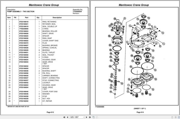
Pump Assembly –
Hydraulic
Wiring Diagram
Alcohol Evaporator Install.
Evaporator Assembly
Valve Assembly – Check
Pump Install – Constant Speed
Pump Assembly –
Two Section
Drive Assembly – Pump
Hydraulic Suction Tube
Installation
(Not Available As Assembly)
Drive Line Assembly
Drive Line Assembly
Neutral Safety Switch
Installation
Control Valve Group – Lower
Hydraulic Lines Installation –
Outrigger
Valve Installation – Control
– Outrigger
Valve Assembly – 4 Stack
Outrigger Solenoid
Valve Assembly – Outrigger Selector
Complete Assembly
Valve Assembly – Solenoid
Schematic
Wiring Diagram
Wiring Diagram – Carrier
Wiring Diagram – S/S
Related Products
-
Grove Crane 1.8 Gb YB Series Collection Parts Document PDF
Original price was: 300.70Current price is: 70. USDThis is an offline spare parts catalog, you need to use this to sell the spare parts and it can help you a little with assembly. It’s from a manufacturer and the best in the world.Hot-77%
REALEASE :
REALEASE :
-
Grove Crane AT ATS Series Collection Parts Document PDF 447 MB
Original price was: 400.70Current price is: 70. USDIf you are a technician, You will need to use this product to repair your vehicleHot-83%
REALEASE :
REALEASE :
-
Grove Parts Document Crane 7.82 Gb TM TMS TT TTS Series Collection PDF
Original price was: 400.250Current price is: 250. USDThis is an offline spare parts catalog, you need to use this to sell the spare parts and it can help you a little with assembly. It’s from a manufacturer and the best in the world.Hot-38%
REALEASE :
REALEASE :
-
Grove GMK EPC Spare Part Catalog Manual 2023 PDF EN DE
Original price was: 600.70Current price is: 70. USDThis is an offline spare parts catalog, you need to use this to sell the spare parts and it can help you a little with assembly. It’s from a manufacturer and the best in the world.Hot-88%
REALEASE :
REALEASE :
-
Grove RT EPC Spare Parts Catalog Manual 2023 PDF EN
Original price was: 2,000.540Current price is: 540. USDThis is an offline spare parts catalog, you need to use this to sell the spare parts and it can help you a little with assembly. It’s from a manufacturer and the best in the world.Hot-73%
REALEASE :
REALEASE :
-
Grove Crane RT GRT Series Collection Parts Document PDF 43 GB
Original price was: 500.340Current price is: 340. USDThis is an offline spare parts catalog, you need to use this to sell the spare parts and it can help you a little with assembly. It’s from a manufacturer and the best in the world.Hot-32%
REALEASE :
REALEASE :
-
Grove Crane 2024 Collection Parts Document 72.1 GB PDF
Original price was: 1,200.840Current price is: 840. USDThis is an offline spare parts catalog, you need to use this to sell the spare parts and it can help you a little with assembly. It’s from a manufacturer and the best in the world.Hot-30%
REALEASE :
REALEASE :
-
Grove Parts Document Crane GMK Series Collection 17.1 GB PDF
Original price was: 500.290Current price is: 290. USDThis is an offline spare parts catalog, you need to use this to sell the spare parts and it can help you a little with assembly. It’s from a manufacturer and the best in the world.Hot-42%
REALEASE :
REALEASE :