
10 ITEMSVIEW CART


Total: 675.00
Expert Support
Full Speed
100% Working
30 USD
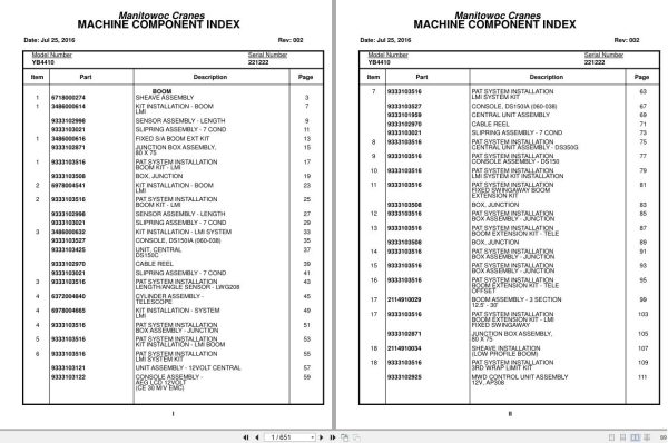
Contents:
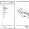
Boom
Sheave Assembly
Kit Installation – Boom
Lmi
Sensor Assembly – Length
Slipring Assembly – 7 Cond
Fixed S/A Boom Ext Kit
Junction Box Assembly,
80 X 75
Pat System Installation
Boom Kit – Lmi
Box, Junction
Kit Installation – Boom
Lmi
Pat System Installation
Boom Kit – Lmi
Sensor Assembly – Length
Slipring Assembly – 7 Cond
Kit Installation – Lmi System
Console, Ds150ia (060-038)
Unit, Central
Ds150c
Cable Reel
Slipring Assembly – 7 Cond
Pat System Installation
Length/Angle Sensor – Lwg208
Cylinder Assembly –
Telescope
Kit Installation – System
Lmi
Pat System Installation
Box Assembly – Junction
Pat System Installation
Kit Installation – Lmi Boom
Pat System Installation
Lmi System Kit
Unit Assembly – 12volt Central
Console Assembly –
Aeg Lcd 12volt
(Ce 30 M/V Emc)
Pat System Installation
Lmi System Kit
Console, Ds150ia (060-038)
Central Unit Assembly
Cable Reel
Slipring Assembly – 7 Cond
Pat System Installation
Central Unit Assembly – Ds350g
Pat System Installation
Console Assembly – Ds150
Pat System Installation
Lmi System Kit Installation
Pat System Installation
Fixed Swingaway Boom
Extension Kit
Box, Junction
Pat System Installation
Box Assembly – Junction
Pat System Installation
Boom Extension Kit – Tele
Box, Junction
Pat System Installation
Box Assembly – Junction
Pat System Installation
Box Assembly – Junction
Pat System Installation
Boom Extension Kit – Tele
Offset
Boom Assembly – 3 Section
12.5′ – 30′
Pat System Installation
Boom Extension Kit – Lmi
Fixed Swingaway
Junction Box Assembly,
80 X 75
Sheave Installation
(Low Profile Boom)
Pat System Installation
3rd Wrap Limit Kit
Mwd Control Unit Assembly
12v, Ap308
Extension Installation –
10′ Jib Boom
Pat System Installation
Junction Box Assembly, Mwd
Pat System Installation
A2b Weight And Chain Assembly
Pat System Installation
Wiring Diagrams
Hook Block Assembly – 11 Ton
Socket, Open Wedge
(5/8” Rope)
(Complete Assembly)
Light Installation – Boom
System Installation – A2b
System Installation – A2b
Kit Installation – Load Moment
Indicator –
(For Reference Only)
(Domestic)
Pat System Installation
Superstructure
Hoist Assembly
Carrier Assembly –
Primary
Carrier Assembly –
Secondary
Motor Assembly – Hydraulic
Valve Assembly – Motor
Control
Valve Assembly – Control
Valve Assembly – Two
Section
Valve Assembly – Control
Valve Assembly – Three
Section
Unit Assembly –
Steering Control
Bearing Bolt Installation
Cylinder Assembly – Lift
Swivel Installation –
Electric And Hydraulic
Cylinder Assembly – Master
Valve Assembly – Park Brake
(Complete Assembly)
Cylinder Installation –
Lift
Shaft Installation –
Boom Pivot
Hoist Installation
Valve Assembly – Priority
Valve Assembly –
Dual Counterbalance
Control Valve And Linkage
Installation
Valve Assembly – Outrigger
Solenoid
Valve Assembly – Selector
Swivel Assembly –
Electric And Hydraulic
Swivel Assembly – 6 Port
Hydraulic
Ring Assembly – Slip
16 Conductor
Hydraulic Lines Installation –
Supply, Pressure And Return
With Oil Cooler
Hydraulic Lines
Installation – Outrigger
Hydraulic Lines Installation –
Swing
Hydraulic Lines Installation –
Lift
Hydraulic Lines Installation –
Telescope
Hydraulic Lines Installation –
Hoist
Hydraulic Lines Installation –
Pressure Check Panel
Rope – 9/16″ Dia Wire
Binder Installation
Superstructure Cab
Panel Assembly – Fuse And
Relay
Harness Assembly – Fuse
And Relay
Top Assembly – Open Cab
Harness Assembly – Relay
Panel To Front Console
Instruments And Lights
Installation
Electrical System Installation
Panel Installation – Fuse And
Relay
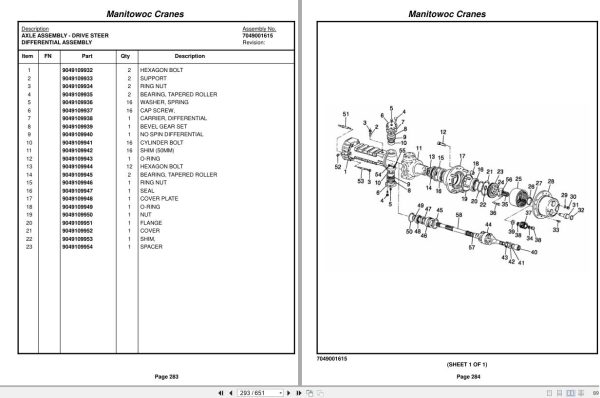
Lowerworks/Carrier
Axle Assembly – Drive
Steer
Axle Assembly – Drive
Steer
Axle Assembly – Drive
Steer
Carrier Housing Parts
Axle Assembly – Drive
Steer
Differential Assembly
Axle Assembly – Drive
Steer
Axle Shaft Assembly
Axle Assembly – Drive
Steer
Disk Assembly
Cylinder Assembly – 3″ Steer
(Complete Assembly)
Brake And Spindle Assembly –
Rh Hub
Hub Assembly
Reservoir Assembly – Hydraulic
(Complete Assembly)
Filter Assembly – Return
Drive Line Assembly
Chamber Assembly – Brake
Cleaner Assembly – Air
Harness Assembly – Carrier
Decal Kit – Standard
Radiator Assembly
Axle Installation –
Drive/Steer
Brake And Spindle Assembly –
Lh Hub
Hub Assembly
Rear Steer Installation
Drive Assembly – Swing
Reducer Assembly – Planetary
Gear
Brake Assembly
Motor Assembly – Orbit
Valve Assembly – Cross
Relief
Cylinder Assembly – 3″ Steer
(Complete Assembly)
Engine Installation –
(For Reference Only)
Battery Installation
Cylinder Assembly-3″ Outrigger Extension
(Complete Assembly)
Hydraulic And Fuel Tank
Installation – Diesel
Drive Line Installation
Frame Section
Stud Installation
Brake Installation – Park
Hydraulic Lines Installation –
Park Brake
Air Cleaner – Exhaust
Installation
Switch Modified –
Turn Signal
Outrigger Installation
Hydraulic Lines Installation –
Brake Lines
Cylinder Assembly-3″ Outrigger Extension
(Complete Assembly)
Exterior Light And Warning
Devices Installation
Cooler Installation – Oil
Hydraulic Lines Installation –
Front And Rear Steer
Heater Installation – Block
Hood Assembly – Engine
Post Installation – Deck
Cover Installation –
Open Cab
Tie Down Installation –
Hook Block
Tire And Wheel Installation
Lug Nut Installation
Deck Cover Installation
Without Tow Winch
Cover Assembly – Tool Box
Quick Start Installation
Radiator Installation
Hood Installation – Engine
Mirrors Installation
Kit, Hardware
Engine Component Assembly –
Cummins With Ford C-6 Transmission
(Not Available As Assembly)
Support Installation – Pump
Pump Assembly – Gear
Hub Assembly
Engine Assy-Cummins 4b3.9
Transmission Rework
Transmission-Ford C6
Case & Extension Assy. Group
Clutch, Direct Drive Group
Forward Clutch Group
Forward Hub & Gear Group
Reverse Clutch Group
Rev.Planet& Output Shaft Group
Control Linkage Group
Servo & Band Group
Control Valve Body Group
Rear Extension Housing Group
Transmission Kit
Electrical System Installation
Harness Assembly – Engine
Hub Assembly
Carrier/Frame Cab
Shifter Assembly
Panel Assembly
Harness Assembly – Front
Console
Diode Block Assy
Heater Assembly – 12 Volt
Mirror Head And Loop
Assembly – Stainless Steel
Harness Assembly – Boom
Light
Harness Assembly – Swivel
To Boom
Accelerator Pedal Assy
Accelerator Pedal Design “B”
Accelerator Pedal Design “A”
Seat Installation
Shifter Installation
Extinguisher Installation
– Fire
Defroster Installation – Heater And
Specs/Schematics
Electrical Schematic
Hydraulic Schematics

REALEASE :
REALEASE :

REALEASE :
REALEASE :

REALEASE :
REALEASE :

REALEASE :
REALEASE :

REALEASE :
REALEASE :

REALEASE :
REALEASE :

REALEASE :
REALEASE :

REALEASE :
REALEASE :
 Automotive - Heavy Equipment - Truck & Bus - Forklift - Crane