
0 ITEMSVIEW CART

✓
Expert Support
✓
Full Speed
✓
100% Working
Hagie Self-Propelled Sprayer STS10 STS12 Repair Technical Manual TM149219
Size: 70.11 MB
Format: PDF
Language: English
Brand: Hagie
Type of Machine: Self-Propelled Sprayer
Type of Manual: Repair Technical Manual
Model: Hagie STS10 STS12 Self-Propelled Sprayer
S.N. 10S019001—
S.N. 12S019001—
Part Number: TM149219
Publication Date: 2021
Number of Pages: 700 Pages
50 USD
- Description
Description
Contents:
General Information
Safety
Recognize Safety Information
Understand Signal Words
Handle Fluids Safely—Avoid Fires
Prevent Battery Explosions
Prepare for Emergencies
Handling Batteries Safely
Handle Agricultural Chemicals Safely
Service and Operate Chemical Sprayers Safely
Avoid Contact with Agricultural Chemicals
Clean Vehicle of Hazardous Pesticides
Park Machine Safely
Support Machine Properly
Wear Protective Clothing
Work in Clean Area
Service Machines Safely
Work In Ventilated Area
Illuminate Work Area Safely
Replace Safety Signs
Use Proper Lifting Equipment
Avoid High-Pressure Fluids
Avoid Static Electricity Risk When Refueling
Wait Before Opening High-Pressure Fuel System
Service Accumulator Systems Safely
Remove Paint Before Welding or Heating
Avoid Heating Near Pressurized Fluid Lines
Service Tires Safely
Follow Tire Recommendations
Avoid Harmful Asbestos Dust
Practice Safe Maintenance
Use Proper Tools
Construct Dealer-Made Tools Safely
Decommissioning — Proper Recycling and Disposal of Fluids and Components
Live With Safety
Servicing Electronic Control Units
Welding Near Electronic Control Units
Keep Electronic Control Unit Connectors Clean
Precautions for Welding
Clean Exhaust Filter Safely
Specifications
Essential or Recommended Tools
Machine Specifications
Machine Dimensions—Use Operators Manual
Sealants and Adhesives Cross-Reference Chart
Unified Inch Bolt and Screw Torque Values
Metric Bolt and Screw Torque Values
Face Seal Fittings Assembly and Installation—All Pressure Applications
Metric Face Seal and O-Ring Stud End Fitting Torque Chart—Standard Pressures
Metric Face Seal and O-Ring Stud End Fitting Torque Chart—High-Pressure Applications
SAE Face Seal and O-Ring Stud End Fitting Torque Chart—Standard Pressures
SAE Face Seal and O-Ring Stud End Fitting Torque Chart—High Pressure Applications
Four Bolt Flange Fittings Assembly and Installation—All Pressure Applications
SAE Four Bolt Flange Cap Screw Torque Values—Standard Pressure Applications
SAE Four Bolt Flange Cap Screw Torque Values—High Pressure Applications
External Hexagon Port Plug Torque Chart
External Hollow Hexagon Port Plug Torque Chart
JIC 37° Flared Fittings
Tune-Up and Adjustment
Tune-Up and Adjustment
Care and Maintenance of Belts
Defective Belts
Nitrogen Tool Bar (NTB) Lift Arm Pin Adjustment (If equipped)
Fuel and Lubricants
Essential or Recommended Tools
Diesel Fuel
Lubricity of Diesel Fuel
Diesel Engine Coolant (engine with wet sleeve cylinder liners)
Operating in Warm Temperature Climates
John Deere COOL-GARD™ II Coolant Extender
Water Quality for Mixing with Coolant Concentrate
Testing Coolant Freeze Point
Diesel Exhaust Fluid (DEF) — Use in Selective Catalytic Reduction (SCR) Equipped Engines
Storing Diesel Exhaust Fluid (DEF)
Testing Diesel Exhaust Fluid (DEF)
Disposal of Diesel Exhaust Fluid (DEF)
John Deere Break-In Plus™ Engine Oil — Interim Tier 4, Final Tier 4, Stage IIIB, Stage IV, and Stage V
Diesel Engine Oil — Interim Tier 4, Final Tier 4, Stage IIIB, Stage IV, and Stage V
Grease
Suspension and Steering Grease
Hydrostatic and Hydraulic Drive Oil
Planetary Hub OilEngine
Engine
Essential or Recommended Tools
Other Material
Specifications
John Deere Engine Repair—Use CTM
Remove and Install Engine
Remove and Install Serpentine Belt
Serpentine Belt Routing
Remove and Install Hood Actuator
Remove and Install Hood
Remove and Install Flex Plate
Cooling System
Essential or Recommended Tools
Specifications
Drain, Flush, and Fill Cooling System
Remove and Install Cooling Package
Remove and Install Cooling Fan
Remove and Install Fan Drive Motor
Remove and Install Coolant Surge Tank
Remove and Install Radiator
Test Radiator and Coolant Tank Cap
Remove and Install Front Hood
Exhaust System
Other Material
Specifications
Remove and Install Diesel Oxidation Catalyst (DOC) and Diesel Particulate Filter (DPF)
Remove and Install Decomposition Tube
Remove and Install Selective Catalytic Reduction (SCR) Converter
DEF Tank Exploded View
Remove and Install Diesel Exhaust Fluid (DEF) Tank
Remove and Install Diesel Exhaust Fluid (DEF) Tank Header
Remove and Install Diesel Exhaust Fluid (DEF) Injection Pump
Remove and Install Diesel Exhaust Fluid (DEF) Injection Pump Filter
Remove and Install DEF Dosing InjectorFuel and Air
Diesel Fuel System
Specifications
Clean and Inspect Fuel Tank
Replace Fuel Filter, Fuel Pump, and Bleed Fuel System
Remove and Install Fuel Tank
Remove and Install Fuel Cooler
Air Intake System
Essential or Recommended Tools
Turbocharger Repair—Use CTM
Remove and Install Air Filter Assembly
Remove and Install Charge Air CoolerElectrical System
Battery
Essential or Recommended Tools
Specifications
Battery Safety
Prevent Damage to Electrical Systems
Check Electrolyte Specific Gravity
Charging Batteries
Connecting Battery Cables
Battery Replacement
Harness and Connector Repair
Essential or Recommended Tools
Other Material
Use Electrical Insulating Compound
Using High-Pressure Washers
Electrical System Visual Inspection
Electrical Connector / Wiring Harness Handling and Repair
Installation of Repair Wire Assembly (RWA)
Repair Procedure R-A
Repair Procedure R-B
Repair Procedure R-C
Repair Procedure R-D
Repair Procedure R-E
Repair Procedure R-F
Repair Procedure R-G
Repair Procedure R-I
Repair Procedure R-J
Repair Procedure R-K
Repair Procedure R-M
Repair Procedure R-N
Repair Procedure R-AE
Repair Procedure R-AF
Repair Procedure R-AG
Repair Procedure R-AH
Repair Procedure R-AI
Repair Procedure R-AJ
Repair Procedure R-AK
Repair Procedure R-AL
Repair Procedure R-AM
Repair Procedure R-AN
Repair Procedure R-AO
Repair Procedure R-AP
Repair Procedure R-AQ
Charging Circuit
Specifications
Remove and Install Alternator
Starting Circuit
Specifications
Remove and Install Starting Motor
Fuses and Relays
Replacing Fuses and Relays
Lighting
Safety Rules When Replacing Halogen Bulbs
Remove and Install Operators Station Front Roof Light Assemblies
Remove and Install Night Spray Option Lights
Remove and Install Rotary Beacon
Rotary Beacon Bulb Replacement
Replace Flasher Module
Remove and Install Front Head Light Assemblies
Remove and Install Rear Flasher Assemblies
Remove and Install Center Boom Front Light Assemblies
Remove and Install Rear Hood Lights
Chassis Control System
Other Material
Remove and Install Hydraulic Oil Level and Temperature Sensor
Remove and Install Wheel Speed Sensor
Remove and Install Fuel Level Sensor
Remove and Install Main Cab Control Unit
Remove and Install Expansion Module 1
Remove and Install Expansion Module 2
Remove and Install Primary Drive Control Unit
Remove and Install Data Transfer Module (If Equipped)
Remove and Install SSU Control Unit (If Equipped)
Engine Control System
Replace Engine Sensors and Switches—Use CTM
Remove and Install Engine Control Unit (ECU)
Spray Rate Control System
Remove and Install Solution Pressure Sensor
Remove and Install Agitation Pressure Sensor
Boom Control System
Remove and Install Norac Valve Module
Remove and Install Boom Control Unit Expansion Modules—27 m and 30 m (90 ft and 100 ft)
Remove and Install Primary Boom Control Unit— 27 m and 30 m (90 ft and 100 ft)
Remove and Install Norac Input Module—27 m and 30 m (90 ft and 100 ft)
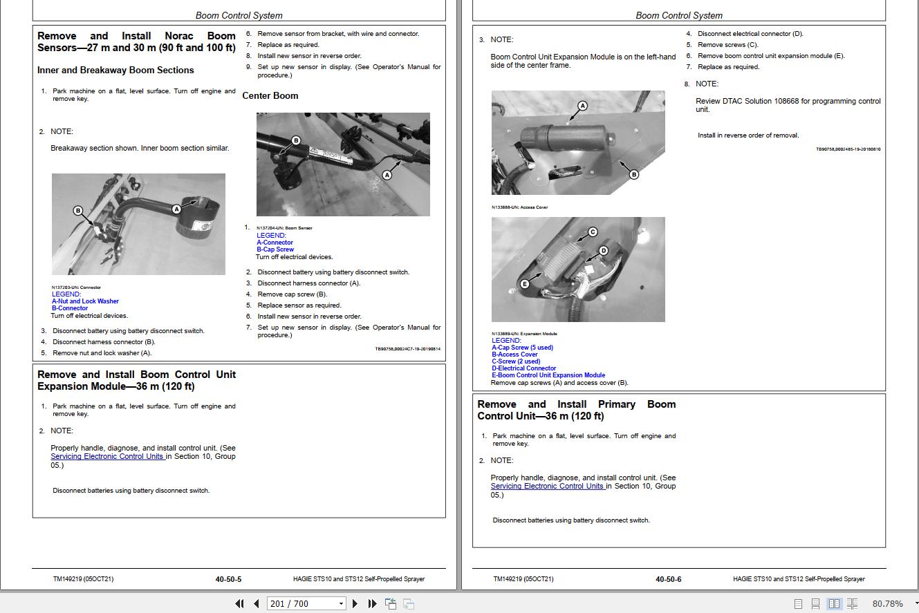
Remove and Install Norac Boom Sensors—27 m and 30 m (90 ft and 100 ft)
Remove and Install Boom Control Unit Expansion Module—36 m (120 ft)
Remove and Install Primary Boom Control Unit—36 m (120 ft)
Remove and Install Norac Boom Sensors—36 m (120 ft)
Remove and Install Boom Height Position Sensor—36 m (120 ft)
Remove and Install Boom Fold Position Sensors—36 m (120 ft)
Remove and Install Boom Level Position Sensor—36 m (120 ft)
Remove and Install Norac Input Module—36 m (120 ft)
Cab Components
Remove and Install Right-Hand Side Pillar Gauges
Remove and Install Steering Column Multi-Function Lever
Remove and Install Selection Key Pad
Remove and Install Console Switch Panel Toggle Switches
Remove and Install Side and Rear Console Power Outlets
Remove and Install Emergency Stop Switch
Remove and Install Parking Brake Switch
Remove and Install Deceleration Pedal
Remove and Install Key Switch
Remove and Install Side Mirrors Control Switch
Remove and Install Machine Display Unit
Remove and Install Throttle Switch
Remove and Install Radio Keypad
Remove and Install Hazard Light Switch, Light Switch, and Turn Signal Indicator
Remove and Install Climate Control Unit
Remove and Install Microphone
Remove and Install Dome Light
Remove and Install Wiper Motor Timer
Remove and Install Wiper Motor
Remove and Install Radio
Remove and Install Speakers
Remove and Install Antenna
Remove and Install Spray System ConsolePower Train
Hydrostatic Drive Pump
Essential or Recommended Tools
Service Equipment and Tools
Other Material
Specifications
Emergency Tow Procedure
Start-Up Procedure After Hydraulic or Hydrostatic Repair
Hydraulic and Hydrostatic System Flushing Procedure
Remove and Install Hydrostatic Drive Pump
Replace Hydrostatic Drive Pump Shaft Seal
Remove and Install Hydrostatic Drive Pump High-Pressure Relief Valves
Remove and Install Hydrostatic Drive Pump Charge Pressure Relief Valve
Remove and Install Hydrostatic Drive Pump Pressure Limiter Valves
Remove, Repair, and Install Hydrostatic Pump Control Module
Replace Hydrostatic Drive Pump Filter
Repair Hydrostatic Drive Pump Filter Adapter
Hydrostatic Drive Pump Charge Pump Exploded View
Disassemble and Assemble Hydrostatic Drive Pump Charge Pump
Disassemble and Assemble Hydrostatic Drive Pump
Hydrostatic Drive Motor
Other Material
Specifications
Remove and Install Hydrostatic Drive Motor Cover
Remove and Install Hydrostatic Drive Motor
Replace Hydrostatic Drive Motor Shaft Seal
Final Drive
Essential or Recommended Tools
Other Material
Specifications
Drain and Fill Planetary Hub
Remove and Install Planetary Final DriveSteering and Brakes
Steering
Essential or Recommended Tools
Other Material
Specifications
Replace Steering System In-Line Filter
Remove and Install Steering Command Control Unit
Remove and Install Steering Cylinder
Remove and Install Steering Cylinder Locking Solenoid Valves and Coils
Remove and Install Steering Arms
Phase Steering Cylinders—Manually
Remove and Install Steering Valve
Remove and Install Steering Input Device (SID) Sensor
Check and Adjust Toe-In
Remove and Install Proximity Sensors
Brakes
Specifications
Remove and Install Park Brake—Ladder Valve
Disassemble and Assemble Park Brake—Ladder ValveSuspension and Tread Adjust
Suspension
Essential or Recommended Tools
Other Material
Specifications
Remove and Install Air Suspension Control Valve
Remove and Install Air Bag Assemblies
Remove and Install Tread Adjust Sensors
Remove and Install Tread Adjust Shim Pads
Remove and Install Leg Suspension
Remove and Install Leg Suspension Bearings
Remove and Install Suspension Tower Shafts
Remove and Install Suspension Tower Shaft Bushings
Remove and Install Lower Air Bag Plate and Bearings
Remove and Install Fenders and Fender Brackets
Tread Adjust Valves
Specifications
Remove and Install Tread Adjust Valves
Disassemble and Assemble Tread Adjust Valve
Tread Adjust Cylinders
Other Material
Specifications
Remove and Install Hydraulic Tread Adjust Cylinders
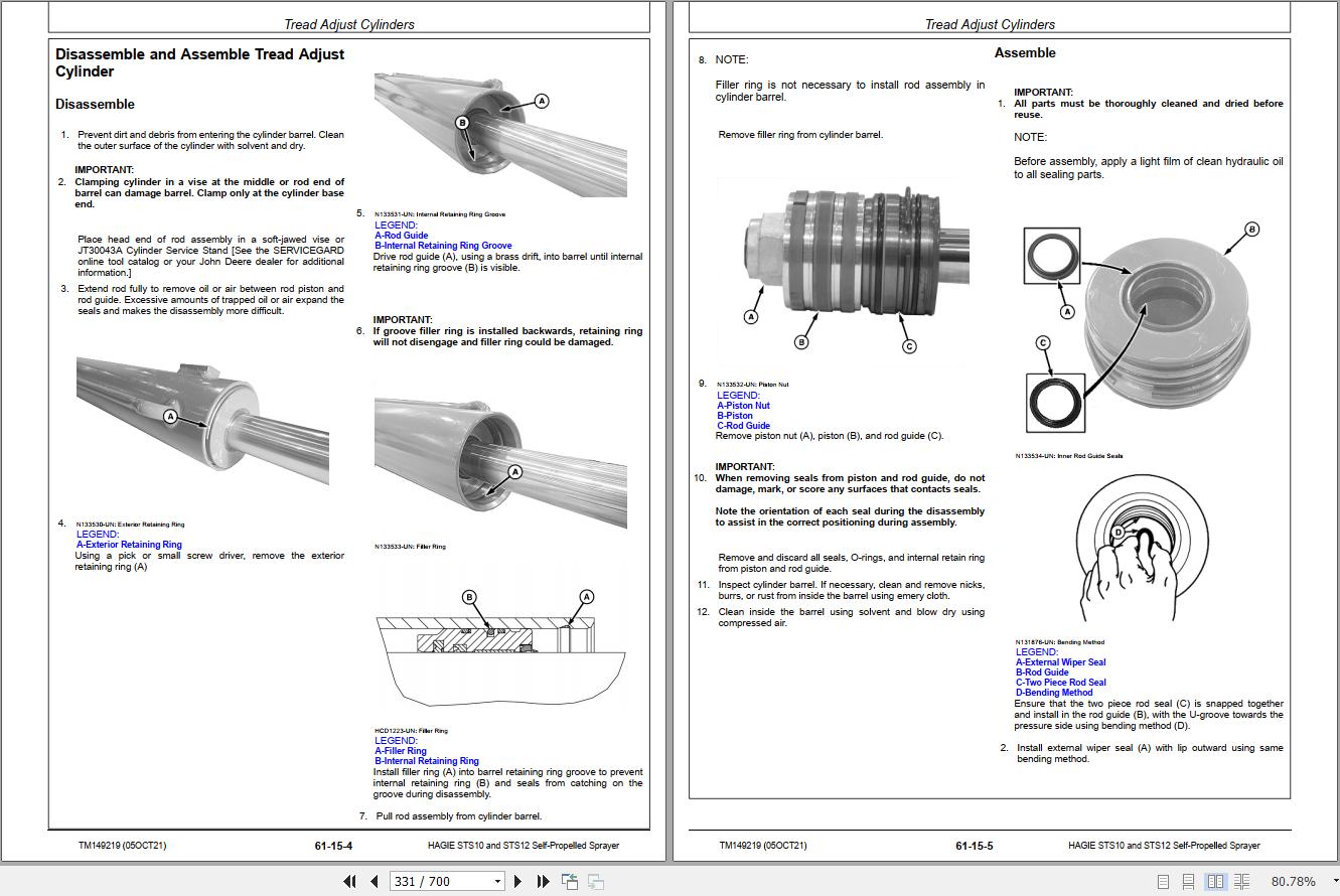
Disassemble and Assemble Tread Adjust Cylinder
Wheels
Other Material
Specifications
Remove and Install WheelHydraulic System
Hydraulic Reservoir
Essential or Recommended Tools
Specifications
Drain and Fill Hydraulic Reservoir
Remove and Install Hydraulic Reservoir Sight Gauge
Remove and Install Return Hydraulic Filter
Remove and Install Hydraulic Reservoir
Connecting Vacuum Pump to Hydraulic Reservoir
Hydraulic Pumps
Other Material
Specifications
Pump Identification
Relieve Hydraulic System Pressure
Remove and Install Auxiliary Drive Pump
Remove and Install Engine Cooling Fan Hydraulic Pump
Remove and Install Solution Pump Hydraulic Pump
Hydraulic Valves
Essential or Recommended Tools
Specifications
Remove and Install All-Wheel Steer Valve
Disassemble and Assemble All-Wheel Steer Valve
Remove and Install Solution Pump Control Valve
Disassemble and Assemble Solution Pump Control Valve
Remove and Install Pressure Washer Pump Valve
Disassemble and Assemble Pressure Washer Pump Valve
Remove and Install Side Fill Valve
Disassemble and Assemble Side Fill Valve
Remove and Install Boom Lift and Fold Valve—27 m and 30 m (90 ft and 100 ft)
Disassemble and Assemble Boom Lift and Fold Valve—27 m and 30 m (90 ft and 100 ft)
Remove and Install Breakaway Valve—27 m and 30 m (90 ft and 100 ft)
Disassemble and Assemble Breakaway Valve—27 m and 30 m (90 ft and 100 ft)
Remove and Install Level Valve—27 m and 30 m (90 ft and 100 ft)
Disassemble and Assemble Level Valve—27 m and 30 m (90 ft and 100 ft)
Remove and Install Boom Fold Valve—36 m (120 ft)
Disassemble and Assemble Boom Fold Valve—36 m (120 ft)
Remove and Install Lift and Level Valve—36 m (120 ft)
Disassemble and Assemble Lift and Level Valve–36 m (120 ft)
Remove and Install Boom Sequence Valve—36 m (120 ft)
Disassemble and Assemble Boom Sequence Valve—36 m (120 ft)
Remove and Install Multifunction Valve (If Equipped)
Hydraulic Cylinders
Essential or Recommended Tools
Service Equipment and Tools
Other Material
Specifications
Remove and Install Ladder Cylinder
Disassemble and Assemble Ladder, Side Fill Lift, and Breakaway Cylinder
Remove and Install Side Fill Lift Cylinder
Remove and Install Lift and Outer Boom Fold Cylinder Bushings—27 m and 30 m (90 ft and 100 ft) (—MY20)
Remove and Install Boom Lift Cylinders—27 m and 30 m (90 ft and 100 ft) (—MY20)
Lift and Outer Fold Cylinders Exploded View—27 m and 30 m (90 ft and 100 ft) (—MY20)
Disassemble and Assemble Lift and Outer Fold Cylinders—27 m and 30 m (90 ft and 100 ft) (—MY20)
Remove and Install Boom Level Cylinder—27 m and 30 m (90 ft and 100 ft) (—MY20)
Boom Level Cylinder Exploded View—27 m and 30 m (90 ft and 100 ft) (—MY20)
Disassemble and Assemble Boom Level Cylinder—27 m and 30 m (90 ft and 100 ft) (—MY20)
Remove and Install Inner Boom Fold Cylinder—27 m and 30 m (90 ft and 100 ft) (—MY20)
Inner Boom Fold Cylinder Exploded View—27 m and 30 m (90 ft and 100 ft) (—MY20)
Remove and Install Outer Boom Fold Cylinder—27 m and 30 m (90 ft and 100 ft) (—MY20)
Remove and Install Breakaway Cylinder—27 m and 30 m (90 ft and 100 ft) (—MY20)
Remove and Install Boom Lift Cylinders—36 m (120 ft)
Remove and Install Boom Level Cylinder—36 m (120 ft)
Remove and Install Inner Boom Fold Cylinder—36 m (120 ft)
Remove and Install Outer Boom Fold Cylinder—36 m (120 ft)
Remove and Install Boom Lock Cylinder—36 m (120 ft)
Remove and Install Wing Roll Cylinder—36 m (120 ft)
Hydraulic Motors
Essential or Recommended Tools
Service Equipment and Tools
Other Material
Specifications
Remove and Install Solution Pump Hydraulic Motor
Solution Pump Hydraulic Motor Exploded View
Disassemble and Assemble Solution Pump Motor
Hydraulic Oil Coolers
Remove and Install Single Core Hydraulic Oil Cooler
Remove and Install Dual Core Hydraulic Oil CoolerSolution Spray System
Component Removal and Installation
Essential or Recommended Tools
Other Material
Specifications
Remove and Install Solution Tank
Remove and Install Rinse Tank
Remove and Install Solution Tank Level Sensor
Remove and Install Solution Tank Level Indicator
Remove and Install Solution Pump and Motor
Remove and Install Nozzle Body
Remove and Install Fence Row Nozzle—27 m and 30 m (90 ft and 100 ft) (—MY20)
Remove and Install Fence Row Nozzle—36 m (120 ft) (—MY20)
Remove and Install Rear Wheel Spray Nozzle
Remove and Install Rinse and Agitation Control Valves
Remove and Install Solution Tank Control Valve
Remove and Install Boom Solution Control Valves
Remove and Install Flowmeter Assembly
Remove and Install Pressure Strainer Assembly
Remove and Install Jet Agitation Nozzle
Remove and Install Rear Wheel Spray Valve
Solution Tank
Empty Tank and Boom Plumbing—Decontaminate Spray Equipment
Service Spray Equipment Safely
Flush Solution Tank and Spray System
Solution Pump
Other Material
Specifications
Solution Pump Exploded View
Disassemble and Assemble Solution Pump
Spray Nozzles
Disassemble and Assemble Nozzle Body
Control Valves
Other Material
Specifications
Disassemble and Assemble Fittings
Repair Check Valves and Strainers
Diagnose and Repair Boom, Rinse, and Agitation Control Valves
Disassemble and Assemble Rinse and Agitation Control Valves
Disassemble and Assemble Boom Solution Control Valves
Diagnose and Repair Solution Tank Control Valve
Disassemble and Assemble Solution Tank Control Valve
Flowmeter
Flowmeter—Exploded View
Calibrate Flowmeter—Use Operators Manual
Rinse Tank
Repair Polyethylene Plastic
Eductor
Eductor Assembly
Remove and Install Eductor System Venturi
Direct Injection
Other Material
Remove and Install Tank Assembly
Remove and Install Mixer Assembly
Remove and Install Pump Assembly
Side Fill
Essential or Recommended Tools
Other Material
Specifications
Remove and Install Side Fill Assembly
Remove and Install Side Fill Pump Motor
Remove and Install Side Fill Pivot Bushing
Remove and Install Side Fill Pump and Motor
Disassemble and Assemble Side Fill Pump Assembly with Motor
Disassemble and Assemble Side Fill PumpPneumatic System
On Board Air Compressor and Reservoir
Other Material
Remove and Install Air Compressor
Tube Fittings
Remove and Install Governor
Remove and Install Air Reservoir
Remove and Install Air Purge Reservoir
Test and Repair Air Connection Leaks
On Board Air Dryer
Remove and Install On Board Air Dryer
Replace Air Dryer Desiccant Filter
Replace Air Dryer Pressure Relief Valve
Foam Marker
Remove and Install Foam Marker Concentrate Tank
Remove and Install Foamer Control Panel
Remove and Install Foam Mixing ChamberOperator`s Station
Cab
Essential or Recommended Tools
Other Material
Specifications
Remove and Install Headliner
Remove and Install Cab Roof
Remove and Install Cab
Remove and Install Instructional Seat
Remove and Install Steering Column Covers
Remove and Install Steering Column
Remove and Install Steering Column Lower Tilt Pedal
Remove and Install Steering Column Telescoping Lever
Remove and Install Steering Column Tilt Cylinders
Remove and Install Rear Console
Remove and Install Side Console
Remove and Install Console Switch Panel
Remove and Install Operators Station Pressure Sensor
Remove and Install Operators Station Air Filter
Remove and Install RESPA Cab Filter Assembly
Controls
Remove and Install Armrest Console
Remove and Install Armrest Control Cover
Remove and Install Multi-Function Lever
Air Conditioning System
Essential or Recommended Tools
Other Material
Specifications
Hose and Tubing O-Ring Connection Torques
R-134a Refrigerant Precautions
System Information
Refrigerant Oil Information
Determine Correct Refrigerant Oil Charge
Add Refrigerant Oil to System
Add Refrigerant Oil to Pressurized System
Discharge Air Conditioning System
Charge Air Conditioning System
Evacuate Air Conditioning System
Purge Air Conditioning System
Flush Air Conditioning System
Leak Test with Dye
Test Volumetric Efficiency
Leak Test Air Quality System Module
Remove and Install Air Conditioner Compressor
Remove and Install Condenser
Remove and Install Receiver-Drier
Remove and Install Expansion Valve
Remove and Install Air Conditioner Binary Switch
Heating System
Other Material
Specifications
Remove and Install Combination Heater Core/Evaporator
Remove and Install Blower Assembly
Remove and Install Heater Control Valve
Remove and Install Air Duct Sensor
Remove and Install HVAC Pressure Switch
Remove and Install Evaporator Coil Temperature Sensor
Remove and Install ATC ECU Module
Remove and Install Air Duct
Air Suspension Seat
Remove and Install Operator Seat
Remove and Install Operator Air Seat Suspension
Remove and Install Operator Seat Riser
Remove and Install Operator Presence Switch
Remove and Install Seat Cushions
Remove and Install Lap Belt
Remove and Install Left-Hand Armrest
Remove and Install Seat Suspension Bellows
Remove and Install Vertical Shock Absorber, Fore/Aft, and Side to Side Adjustment Levers
Remove and Install Vertical Shock Absorber Control Cable
Remove and Install Vertical Shock Absorber
Remove and Install Lateral Shock Absorber
Remove and Install Operator Seat Lateral Rollers
Remove and Install Horizontal Shock Absorber
Remove and Install Fore/Aft Rail Assemblies
Remove and Install Seat Suspension Compressor
Remove and Install Seat Suspension Air Spring
Remove and Install Seat Height Control Switch
Remove and Install Fan Control High, Low, and Off Switch
Remove and Install Fan and Heat Switch
Remove and Install Seat Cushion Angle and Depth Adjustment Levers
Remove and Install Seat Cushion Depth Adjustment Cable
Cab Door and Windshield
Remove and Install Cab Door Latch
Cab Door Catch Adjustment
Remove and Install Windshield, Rear, and Side Window Glass
Remove and Install Cab Door
Remove and Install Foot Latch CablePlatform
Platform
Essential or Recommended Tools
Remove and Install Hand Wash Tank Pump
Remove and Install Washer Fluid Reservoir
Remove and Install Pressure Washer Hose Reel
Remove and Install Pressure Washer Pump
Remove and Install Pressure Washer Drive MotorBoom
Boom-36 m (120 ft)
Specifications
Prepare Sprayer for Service of Spray Boom
Remove and Install Center Frame—36 m (120 ft)
Remove and Install Center Frame Pivot Assembly Bushing—36 m (120 ft)
Remove and Install Center Frame Fold Block Bushing—36 m (120 ft)
Remove and Install Lower Lift Arm Bushings—36 m (120 ft)
Remove and Install Upper Lift Arm Bushings—36 m (120 ft)
Remove and Install Lift Cylinder Bushings—36 m (120 ft)
Remove and Install Boom Level Cylinder Bushings—36 m (120 ft)
Remove and Install Breakaway Boom Section—36 m (120 ft)
Remove and Install Outer Boom Section—36 m (120 ft)
Remove and Install Inner Boom Section—36 m (120 ft)
Remove and Install Inner Boom Lower Bushing—36 m (120 ft)
Remove and Install Inner Wing Fold Bushing—36 m (120 ft)
Boom Adjustment—36 m (120 ft)
Boom-27 m and 30 m (90 ft and 100 ft)
Other Material
Remove and Install Center Frame—27 m and 30 m (90 ft and 100 ft)
Remove and Install Lower Lift Arm Bushings—27 m and 30 m (90 ft and 100 ft)
Remove and Install Upper Lift Arm Bushings—27 m and 30 m (90 ft and 100 ft)
Remove and Install Outer Boom Tip—27 m and 30 m (90 ft and 100 ft)
Remove and Install Breakaway Boom Section—27 m and 30 m (90 ft and 100 ft)
Remove and Install Breakaway Boom Section Bushings—27 m and 30 m (90 ft and 100 ft)
Remove and Install Outer Boom Section—27 m and 30 m (90 ft and 100 ft)
Remove and Install Outer Boom Section Fold Bushing—27 m and 30 m (90 ft and 100 ft)
Remove and Install Inner Boom Section—27 m and 30 m (90 ft and 100 ft)
Remove and Install Center Frame Pivot—27 m and 30 m (90 ft and 100 ft)
Remove and Install Center Frame Pivot Bushings—27 m and 30 m (90 ft and 100 ft)Dealer Fabricated Tools
Dealer Fabricated Tools
DFNXT34—Swash Plate Hold-Down Clamp
DFN21 Pump Support Fixture
DFNXT32—Cab Removal ToolPage Number
Related Products
-
Hagie 2017 DTS10 Electrical Schematic Rev-C 499342 08.2016
Original price was: 40.30Current price is: 30. USDHagie 2017 DTS10 Electrical Schematic Rev-C 499342 08.2016Size: 2.07 MBFormat: PDFLanguage: EnglishBrand: John DeereType of Machine: AgriculturalType of Manual: SchematicModel: Hagie DTS10 2017Date: 08.2016Number of Page: 54 PagesPart Number: 499342-25%
REALEASE :
01.03.2022
REALEASE :
01.03.2022
-
Hagie STS Machine 90 100 Foot Booms Line Diagrams 2014
Original price was: 40.30Current price is: 30. USDHagie STS Machine 90 100 Foot Booms Line Diagrams 2014Size: 1.26 MBFormat: PDFLanguage: EnglishBrand: John DeereType of Machine: AgriculturalType of Manual: SchematicModel: Hagie 90 100 Foot Booms STS MachineDate: 2014Number of Page: 5 Pages-25%
REALEASE :
01.03.2022
REALEASE :
01.03.2022
-
Hagie STS 10 – 16 2016 2017 Raven Line Diagrams
Original price was: 40.30Current price is: 30. USDHagie STS 10 – 16 2016 2017 Raven Line DiagramsSize: 2.92 MBFormat: PDFLanguage: EnglishBrand: John DeereType of Machine: AgriculturalType of Manual: SchematicModel: Hagie 2016 2017 Raven STS 10 – 16Number of Page: 4 Pages-25%
REALEASE :
01.03.2022
REALEASE :
01.03.2022
-
Hagie 2017 STS10-12-14-16 Electrical Schematic Rev-A 499195 05.2016
Original price was: 30.20Current price is: 20. USDHagie 2017 STS10-12-14-16 Electrical Schematic Rev-A 499195 05.2016Size: 1.99 MBFormat: PDFLanguage: EnglishBrand: John DeereType of Machine: AgriculturalType of Manual: SchematicModel: Hagie STS10-12-14-16 2017Date: 05.2016Number of Page: 54 PagesPart Number: 499195-33%
REALEASE :
01.03.2022
REALEASE :
01.03.2022
-
Hagie STS MY2014 2015 System 2019 2020 ST Raven Precision Schematic
Original price was: 40.30Current price is: 30. USDHagie STS MY2014 2015 System 2019 2020 ST Raven Precision SchematicSize: 3.09 MBFormat: PDFLanguage: EnglishBrand: John DeereType of Machine: AgriculturalType of Manual: SchematicModel: Hagie System 2019 2020 ST Raven Precision STS MY2014 2015Number of Page: 6 Pages-25%
REALEASE :
01.03.2022
REALEASE :
01.03.2022
-
Hagie Hi-Tractor STS 16 U1621331001 through U1621331200 Operator Manual 493559 2012
Original price was: 30.20Current price is: 20. USDHagie Hi-Tractor STS 16 U1621331001 through U1621331200 Operator Manual 493559 2012Size: 83.6 MBFormat: PDFLanguage: EnglishBrand: HagieType of Machine: Hi-TractorType of Manual: Operator ManualModel: Hagie STS 16 Hi-TractorDate: 2012Serial Number: U1621331001 through U1621331200Number of Page: 670 PagesPart Number: 493559-33%
REALEASE :
01.07.2022
REALEASE :
01.07.2022
-
Hagie STS Kit 2000-2008 STS10 STS12 AG Leader Line Diagrams
Original price was: 40.30Current price is: 30. USDHagie STS Kit 2000-2008 STS10 STS12 AG Leader Line DiagramsSize: 1.61 MBFormat: PDFLanguage: EnglishBrand: John DeereType of Machine: AgriculturalType of Manual: SchematicModel: Hagie STS10 STS12 AG Leader STS Kit 2000-2008Number of Page: 7 Pages-25%
REALEASE :
01.03.2022
REALEASE :
01.03.2022
-
Hagie STS MY2014 Steering System Schematic
Original price was: 40.30Current price is: 30. USDHagie STS MY2014 Steering System SchematicSize: 0.97 MBFormat: PDFLanguage: EnglishBrand: John DeereType of Machine: AgriculturalType of Manual: SchematicModel: Hagie Steering System STS MY2014Number of Page: 1 Pages-25%
REALEASE :
01.03.2022
REALEASE :
01.03.2022