
0 ITEMSVIEW CART


✓
Expert Support
✓
Full Speed
✓
100% Working
Hangcha Forklift CPCD40-XW99BN to CPYD55-XXH11BN Service Manual 2021
Size: 7.54 MB
Format: PDF
Language: English
Brand: Hangcha
Type of Machine: Internal Combustion Counterbalanced Forklift Truck
Type of Document: Service Manual, Electrical and Hydraulic Diagram
Model: Hangcha XF Series 4t-X5.5t
CPCD40-XW99BN, CPCD45-XW99BN, CPCD50-XXW99BN, CPCD55-XXW99BN
CPCD40-XH8BN, CPCD45-XH8BN, CPCD50-XXH8BN, CPCD55-XXH8BN
CPYD40-XH11BN, CPYD45-XH11BN, CPYD50-XXH11BN, CPYD55-XXH11BN
Date: 2021
Number of Pages: 91 Pages
30 USD
- Description
Description
Contents:
I Power system.
II Driving system
2.1 Summary
2.2 Drive axle assembly
2.3 Drive shaft assy
2.4 Hydraulic transmission gearbox
III Steering system
3.1 Structure introduction
3.2 Technical parameters
3.3 Steering system installation notes
3.4 Fault diagnoses and corrections
3.5 Hydraulic steering gear
3.6 Steering axle
3.7 Steering cylinder
IV Brake system
4.1 Summary
4.2 Data
4.3 Brake inching pedal adjustment
4.4 Parking brake adjustment
4.5 Principle of braking system.
4.6 Brake master cylinder
4.7 Fault diagnoses and corrections
V Hydraulic system
5.1 Main data
5.2 Hydraulic system principle
5.3 Main pump
5.4 Multiway valve
VI Lifting system
6.1 Summary
6.2 Mast debugging data
6.3 Fault diagnosis and corrections
6.4 Removal and adjustment
6.5 Disassembly and installation of lifting cylinder
6.6 Disassembly and installation of tilting cylinder
6.7 Noticing proceeding of debugging
VII. Interactive instrument
7.1 Engine fault information display page
7.2 Forklift operation parameters and interface switching between Chinese and English
7.3 Settings page
7.4 Disassembly and installation
VIII Electrical system
8.1 Control box assembly
8.2 Sens or and relay
8.3 Lighting system
8.4 Electrical schematic diagram
Related Products
-
Hangcha XH Series 6.0t-X10t CPD60-XHY2G-W to CPD100-XHY2G-W Service Manual 2023 EN
50 USDSize: 11.38 MBFormat: PDFLanguage: EnglishBrand: HangchaType of Machine: Electric Forklift TruckType of Manual: Service Manual, Wiring Diagrams, Hydraulic DiagramsModel: Hangcha XH Series 6.0t-X10t Electric Forklift TruckCPD80-XHY2G-W CPD90-XHY2G-W CPD100-XHY2G-W CPD60-XHY2G-W CPD70-XHY2G-WPublication Date: 2023Number of Pages: 134 Pages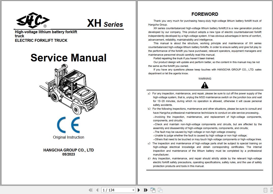
REALEASE :
REALEASE :
-
Hangcha XC Series 2.0t-3.5t CPD20-XD4-SI21 to CPD35-XD6-SI21 Parts Catalog 2026
100 USDSize: 81.37 MBFormat: PDFLanguage: English, ChineseBrand: HangchaType of Machine: Electric Forklift TruckType of Manual: Parts CatalogModel: Hangcha XC Series 2.0t-3.5tCPD20-XD4-SI21 CPD25-XD4-SI21 CPD30-XD4-SI21 CPD35-XD4-SI21CPD20-XD6-SI21 CPD25-XD6-SI21 CPD30-XD6-SI21 CPD35-XD6-SI21Publication Date: 01.2026Number of Pages: 1503 Pages
REALEASE :
REALEASE :
-
Hangcha XH Series 9.0t H90EC-8-XHJG H90EC-7-XHJG Service Manual 2023 EN
50 USDSize: 11.10 MBFormat: PDFLanguage: EnglishBrand: HangchaType of Machine: Forklift TruckType of Manual: Service Manual, Wiring Diagrams, Hydraulic DiagramsModel: Hangcha XH Series 9.0t H90EC-8-XHJG H90EC-7-XHJG Forklift TruckPublication Date: 2023Number of Pages: 105 Pages
REALEASE :
REALEASE :
-
Hangcha XH Series RS4531CH-XHJG RS4531CH-XHJG-C Operation Maintenance Manual 2025 EN
20 USDSize: 20.55 MBFormat: PDFLanguage: EnglishBrand: HangchaType of Machine: Reach StackerType of Manual: Operation And Maintenance ManualModel: Hangcha XH Series RS4531CH-XHJG RS4531CH-XHJG-C Reach StackerPublication Date: 2025Number of Pages: 165 Pages
REALEASE :
REALEASE :
-
Hangcha XR Series 1.5t-3.8t CPCD15-XRG71J to CPD38-XRH5B1 Service Manual 2025 EN
50 USDSize: 11.94 MBFormat: PDFLanguage: EnglishBrand: HangchaType of Machine: Electric Forklift TruckType of Manual: Service Manual, Wiring Diagrams, Hydraulic DiagramsModel: Hangcha XR Series 1.5t-3.8t Electric Forklift TruckCPCD15-XRG71J CPCD18-XRG71J CPCD15-XRG71JF CPCD18-XRG71JF CPCD15-XRG71JB1 CPCD18-XRG71JB1CPCD15-XRW10 CPCD18-XRW10 CPCD15-XRW10F CPCD18-XRW10F CPCD15-XRW10B1 CPCD18-XRW10B1 CPQD15-XRW21CPQD18-XRW21 CPQD15-XRW21F CPQD18-XRW21F CPQD15-XRW21B1 CPQD18-XRW21B1 CPQYD15-XRW21 CPQYD18-XRW21CPQYD15-XRW21F CPQYD18-XRW21F CPQYD15-XRW21B1 CPQYD18-XRW21B1 CPCD15-XRW32F CPCD18-XRW32FCPCD15-XRW32B1 CPCD18-XRW32B1 CPYD15-XRW51F CPYD18-XRW51F CPYD15-XRW51B1 CPYD18-XRW51B1CPCD15-XRH5 CPCD18-XRH5 CPCD15-XRH5F CPCD18-XRH5F CPCD15-XRH5B1 CPCD18-XRH5B1 CPCD15-XRG98CPCD18-XRG98 CPCD15-XRG98F CPCD18-XRG98F CPCD15-XRG98B1 CPCD18-XRG98B1 CPCD20-XRG72 CPCD25-XRG72CPCD20-XRG72F CPCD25-XRG72FCPCD20-XRG72B1 CPCD25-XRG72B1 CPCD20-XRG92 CPCD25-XRG92 CPCD20-XRG92FCPCD25-XRG92F CPCD20-XRG92B1 CPCD25-XRG92B1 CPCD20-XRW10 CPCD25-XRW10 CPCD20-XRW10F CPCD25-XRW10FCPCD20-XRW10B1 CPCD25-XRW10B1 CPCD20-XRG2 CPCD25-XRG2 CPQD20-XRW22 CPQD25-XRW22 CPQD20-XRW22FCPQD25-XRW22F CPQD20-XRW22B1 CPQD25-XRW22B1 CPQYD20-XRW22 CPQYD25-XRW22 CPQYD20-XRW22F CPQYD25-XRW22FCPQYD20-XRW22B1 CPQYD25-XRW22B1 CPCD20-XRW55F CPCD25-XRW55F CPCD20-XRW55B1 CPCD25-XRW55B1 CPCD20-XRW33FCPCD25-XRW33F CPCD20-XRW33B1 CPCD25-XRW33B1 CPYD20-XRW52F CPYD25-XRW52F CPYD20-XRW52B1 CPYD25-XRW52B1CPCD20-XRH5 CPCD25-XRH5 CPCD20-XRH5F CPCD25-XRH5F CPCD20-XRH5B1 CPCD25-XRH5B1 CPCD30-XRG72 CPCD35-XRG72CPCD38-XRG72 CPCD30-XRG72F CPCD35-XRG72F CPCD38-XRG72F CPCD30-XRG72B1 CPCD35-XRG72B1 CPCD38-XRG72B1CPCD30-XRG92 CPCD35-XRG92 CPCD38-XRG92 CPCD30-XRG92F CPCD35-XRG92F CPCD38-XRG92F CPCD30-XRG92B1CPCD35-XRG92B1 CPCD38-XRG92B1 CPCD30-XRW10 CPCD30-XRW10F CPCD35-XRW10F CPCD30-XRW10B1 CPCD35-XRW10B1CPCD30-XRG2 CPCD35-XRG2 CPCD38-XRG2 CPQD30-XRW22 CPQD35-XRW22 CPQD30-XRW22F CPQD35-XRW22F CPQD38-XRW22FCPQD30-XRW22B1 CPQD35-XRW22B1 CPQD38-XRW22B1 CPQYD30-XRW22 CPQYD35-XRW22 CPQYD38-XRW22 CPQYD30-XRW22FCPQYD35-XRW22F CPQYD38-XRW22F CPQYD30-XRW22B1 CPQYD35-XRW22B1 CPQYD38-XRW22B1 CPCD30-XRW55F CPCD35-XRW55FCPCD38-XRW55F CPCD30-XRW55B1 CPCD35-XRW55B1 CPCD38-XRW55B1 CPCD30-XRW33F CPCD35-XRW33F CPCD38-XRW33FCPCD30-XRW33B1 CPCD35-XRW33B1 CPCD38-XRW33B1 CPCD30-XRW52F CPCD35-XRW52F CPCD38-XRW52F CPCD30-XRW52B1CPCD35-XRW52B1 CPCD38-XRW52B1 CPCD30-XRH5 CPCD35-XRH5 CPCD38-XRH5 CPCD30-XRH5F CPCD35-XRH5F CPCD38-XRH5FPublication Date: 2025Number of Pages: 153 Pages
REALEASE :
REALEASE :
-
Hangcha XH Series 9.0t H90EC-8-XHJG H90EC-7-XHJG Operation Maintenance Manual 2023 EN
20 USDSize: 21.14 MBFormat: PDFLanguage: EnglishBrand: HangchaType of Machine: Lithium E-TrucksType of Manual: Operation And Maintenance ManualModel: Hangcha XH Series 9.0t H90EC-8-XHJG H90EC-7-XHJG Lithium E-TrucksPublication Date: 2023Number of Pages: 142 Pages
REALEASE :
REALEASE :
-
Hangcha Forklift PDF Manual 2023 Collection
Original price was: 150.80Current price is: 80. USDThis is a service information package, you will need to use this to repair a vehicleHot-47%
REALEASE :
REALEASE :
-
Hangcha Forklift 2024 Operator Service Manual EPC Spare Parts Catalog PDF 12.6 GB
Original price was: 700.290Current price is: 290. USDThis is a service information package, you will need to use this to repair a vehicleHot-59%
REALEASE :
REALEASE :